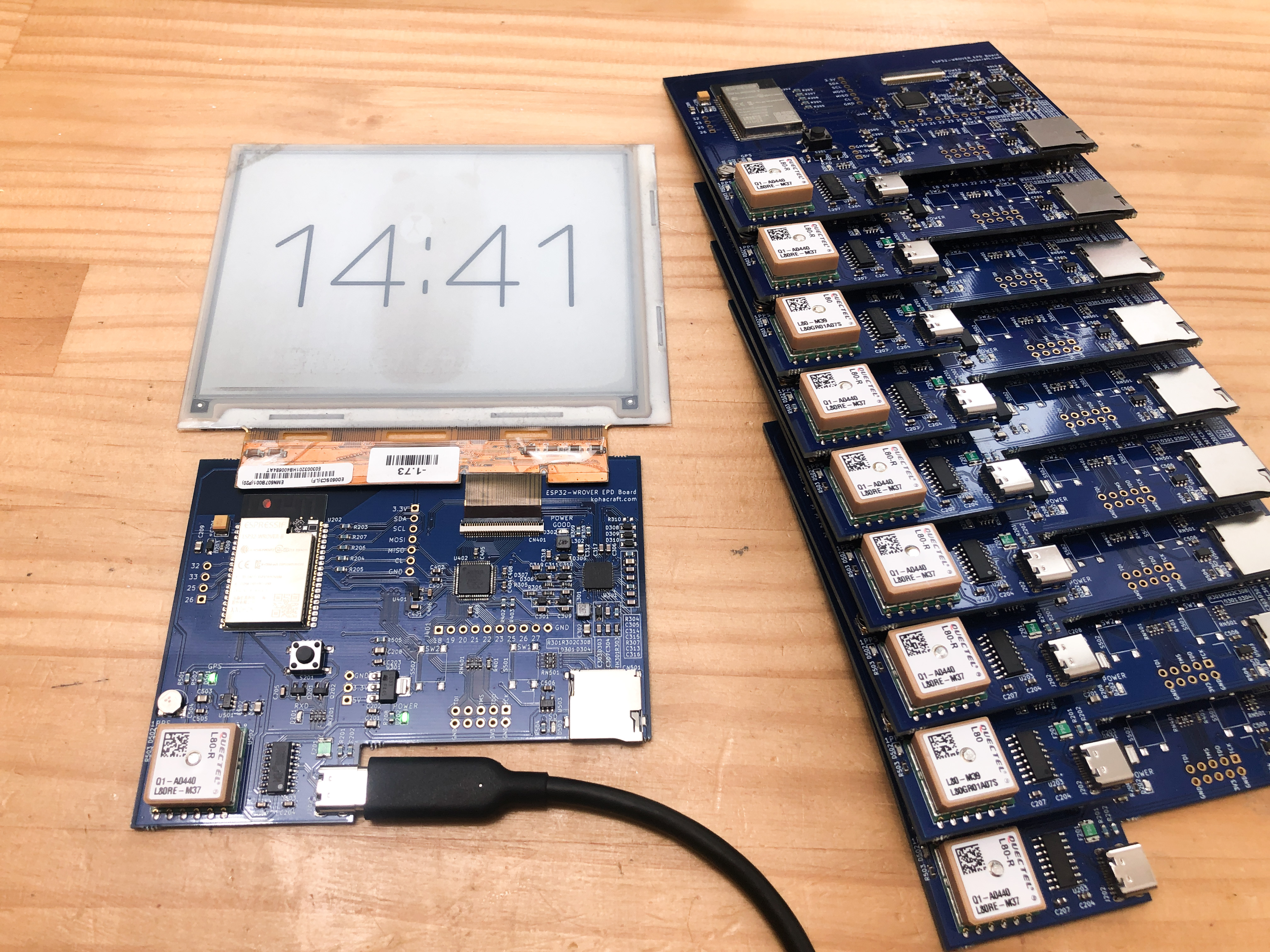
In this project, I would like to integrate the GPS e-paper control PCB into a photo frame and make it into a GPS e-paper clock. Here's a 👇👇 description of the soldering of the GPS e-paper control board that I had made the other day at PCBWay.

Photo frame

This photo frame was perfect for my 5-inch e-paper.

This is where the electronic paper and control board are placed. As it is, there is no cover on the back, so I will use the laser cutter to make one.
Making the back cover of the photo frame

Design the back cover using Illustrator. Design the screw holes and the holes where the cables will exit.

I'm going to make one to try. I use 2.5 mm thick boards of MDF.

The laser cutter cuts with ease.

It takes about a minute to complete the process.
Assembly

The size of the back cover is perfect. Screw it in and you're done.

It was perfect, and I'll make about 10 copies.

It would take about 10 minutes to finish cutting.
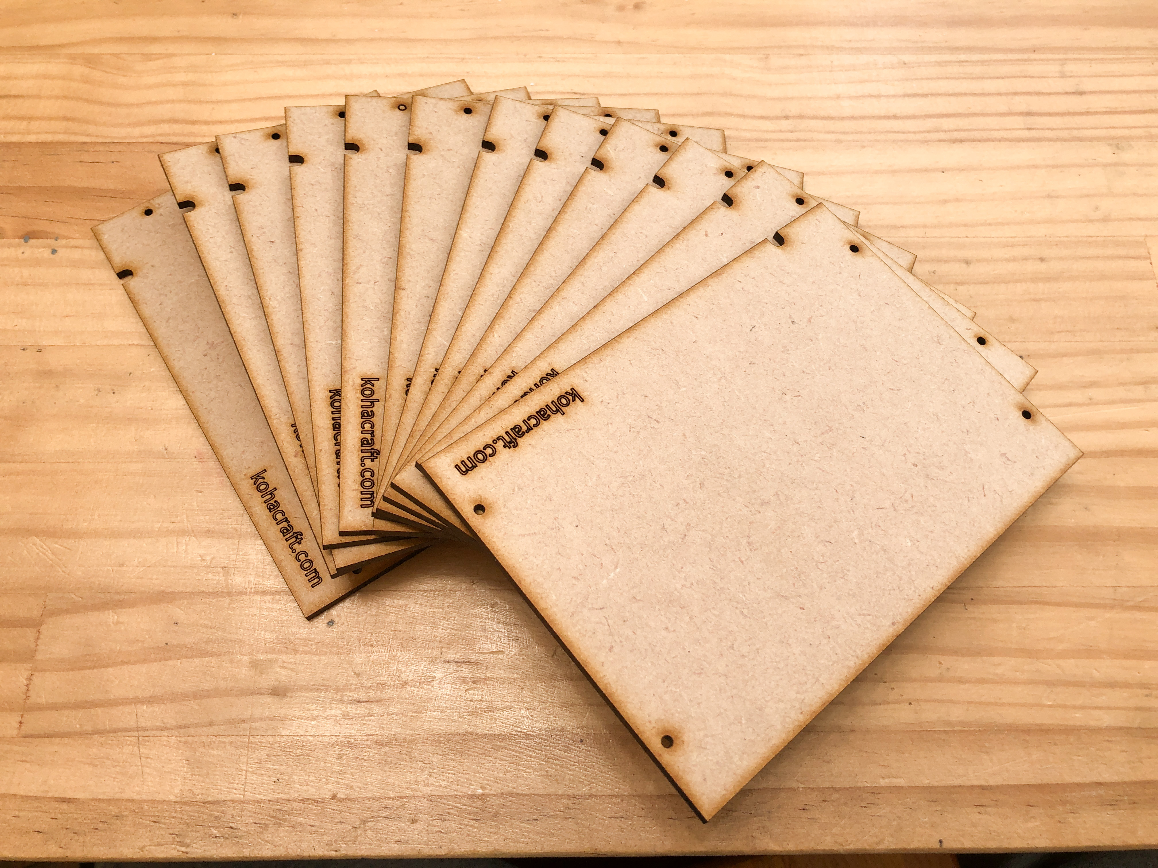
The original back cover is complete.
Adjusting text position

When I put it in the picture frame, I found that the letters were slightly misaligned.

Adjusted the text position programmatically.
Done!!!
The GPS-synchronized e-paper clock is now ready. It will always show you the exact time. The fonts are stored as BMP on the built-in SD card. By rewriting the BMP, we can make the clock with the original font.

By turning your child's writing into a BMP, the child's cute handwriting becomes the dial. If it is your child's or grandchild's character, it is cute and makes you happy.