I made a microphone amplifier that can run on phantom power and can handle high volume.
Circuit
Circuit diagram

This is a microphone amplifier circuit that operates on phantom power. This circuit is based on the circuit of a person who makes professional microphones. Please see here for more details. This is a very informative site about microphones.

The phantom power supply is 48V, which is a pretty high voltage, so the 2SA1015 transistor, which is readily available, is pretty much on the edge of spec. So I decided to use a high voltage transistor MPSA92 that can withstand up to 300V, which I used in the Nixie tube drive circuit.
Designing with KiCad

I designed the board in KiCad. I ordered this board from PCBWay.

Here is the PCBs I received. I received them in 6 days after ordering. PCBWay is fast and does a good job.
Mounting the components
DIP components

This time, only DIP components were used, so it was easy.

The mounting of the components is now complete.
EMC

This is the microphone part.

I have cut the pattern to avoid using the FET amplifier built into the EMC. By doing this, the gain is reduced by a factor of one, so the signal is smaller, but the signal waveform is less likely to clip even at high volume, and the microphone can be configured for high volume.
Not all EMC microphones can be modified in this way, some can and some cannot. After buying a number of mics, I found that this one can be modified.

https://lcsc.com/product-detail/Electret-Condenser-Microphone_INGHAi-GMI9767-36db_C233996.html
.0930. Free access GMI9767-36db datasheet, Package, p...Finished!

The microphone and microphone amplifier are complete.

Connect the XLR connector to this.
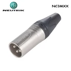
For the XLR connector, I used NEUTRIK's NC3MXX silver, which is metal, shields well, and is durable.
Operation check
The audio interface is ZOOM U-44, and I'll check the operation.

There was little hum noise, and the sound quality was straightforward. It's a pretty good microphone. I'd like to try recording some sounds next time.