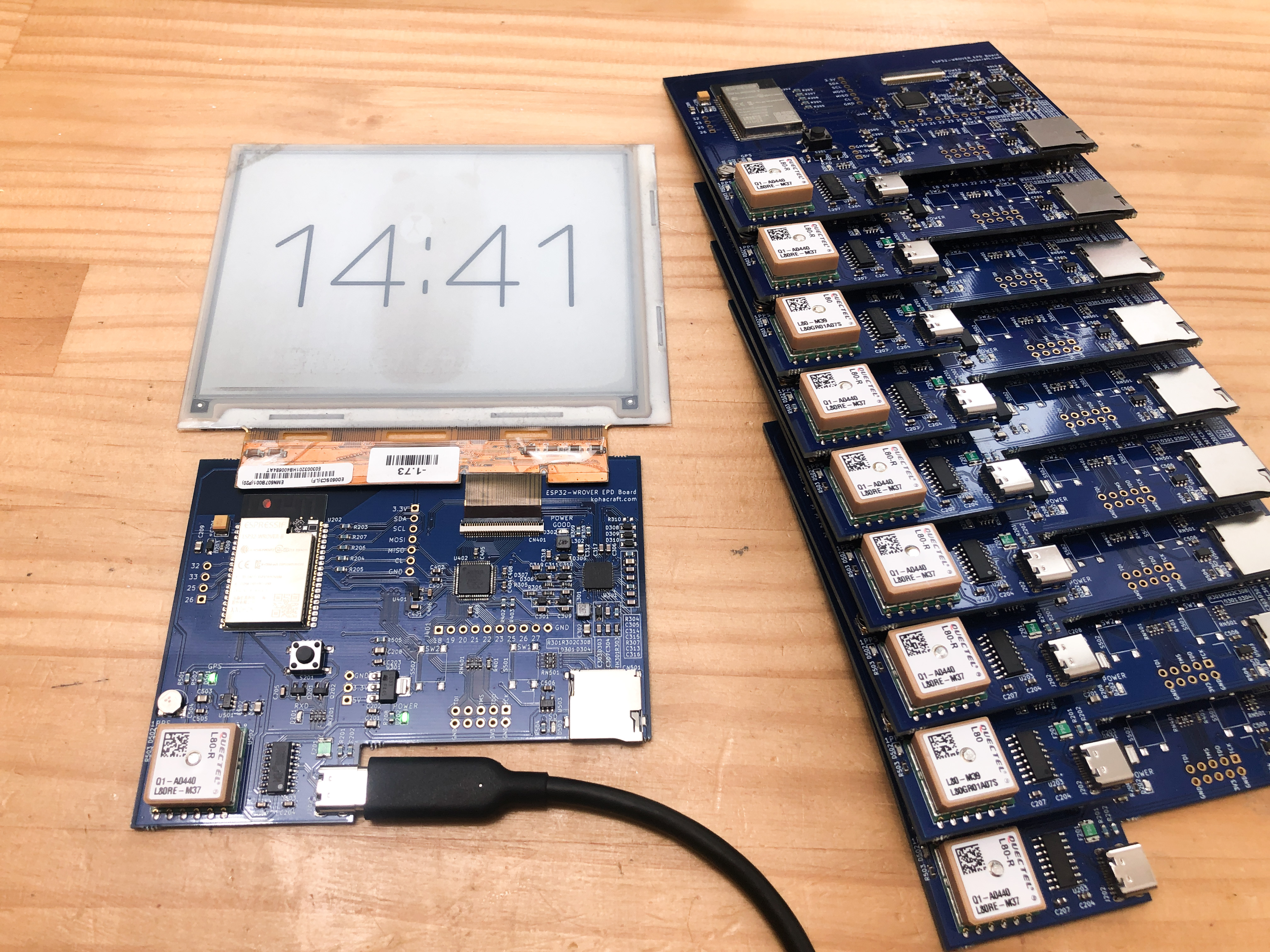
I made a control board for an e-paper that has a GPS module and can keep accurate time at any time.
Printing solder paste
I had the PCB and stencil made by PCBWay. At PCBWay, you can have the stencil cut to any size you want by specifying it when ordering.
When you place your order, write the size you want to cut out in the "Other Special Processing" box, and they will cut it out at that size. In this case, the size of the board was 10 cm square, so I made the stencil 15 cm square. This size is easy to work with and easy to store.
In addition, there are 1mm holes in the four corners of the board and stencil so that you can easily and accurately align the board and stencil by sticking thumbtacks into them. Set up the stencil data to drill holes, and also set the "existing reference point" to "laser will pass through" when ordering. This way, you can be sure that the holes will be drilled into the PCB.
If you stick a thumbtack in to secure it, it will look like this. This thumbtack-based positioning allows the printing of solder paste in precise locations, even on small pads of 0.4mm or 0.5mm pitch ICs.
For the solder paste, we used CHIPQUIK's low melting point lead-free solder paste TS391LT50. The melting temperature is as low as 138°C, allowing for easy reflow in the oven. In addition, TS391LT50 has a finer grain size than general Chinese solder paste, which allows for precise printing.
Print the solder paste with a credit card or other plastic card that you no longer need.
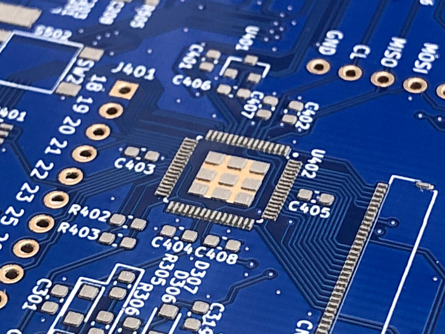
In the center is a QFP component with a pitch of 0.4 mm, and the solder paste is printed very nicely.
Printing of solder paste is now complete.
Component mounting
I use an electric vacuum pick HAKKO 394 instead of tweezers.
Like a vacuum cleaner, it absorbs components with the force of sucking air. Since the components are not pinched from both sides like tweezers, components can be mounted even when the distance between them is narrow.
Picking up components directly from the SMD tape also makes mounting much easier, since components with polarity, such as diodes and LEDs, can always be picked up in a fixed orientation.
The SMD tape feeder was printed with a 3D printer from data found on Thingiverse.
The HAKKO 394 can pick up small to large components.
The GPS module is made of ceramic and is heavy, but it can be firmly attached.
Because of the large number of components this time, it took a whole day to mount the components. If I had mounted it with tweezers, I would not have finished. I highly recommend electric vacuum picks as they can increase work efficiency very much.
Reflow
Reflow in a convection oven, which can be heated by a heater and hot air.
Tescom TSF601 allows you to change the temperature setting even in the middle of heating, so you can adjust the temperature to match the temperature profile of the solder paste while watching the temperature of the thermocouple thermometer installed in the chamber. In this case, I heated the board slowly and longer than the specified time because there is a GPS module on the PCB that is difficult to warm up.
Reflow is completed in about 10 minutes while changing the temperature setting. The Tescom TSF601, which can hold four loaves of bread, has a wide interior and was able to reflow four 10cm square substrates at the same time.
After three reflow cycles, the reflow for 10 PCBs was completed.
Checking the mounting
Check to see if it can be mounted with Eakins' digital microscope.
Here is the IC in a 0.4mm pitch QFP package. No bridges, solder balls, etc. were generated, and the assembly was cleanly mounted.
This is a QFN package with 0.5mm pitch. It looks okay.
0.5 mm pitch connector. It was mounted beautifully.
Operation check
Now that the visual check is complete, we turn on the power and check the operation.
Write to CPLD
This e-paper control board contains a CPLD between the microcontroller (ESP32) and the e-paper so that the parallel controlled e-paper can be drawn via SPI communication. We will check this CPLD.
First, connect the CPLD to the PC via JTAG. There is a pattern on the PCB for attaching connectors, but due to the height limitation, no connectors are attached. So connect it with a test pin. For the test pins, I used P75-E2.
Plug the test pins into the IDC connector of JTAG like this.
Then, place the test pin in contact with the hole in the land of the connector and press down on it from above. This test pin has a built-in spring, so it will make proper contact even if it is tilted slightly.
Check if Quartus Prime can recognize CPLD.
The CPLD was recognized normally. Now let's try to write the firmware.
I was able to write normally. Now I know that CPLD is functioning properly.
Write to ESP32
Write the GPS clock program in the Arduino IDE to the ESP32 on the board. It was written successfully and the serial monitor showed the time information acquired by GPS. Both ESP32 and GPS worked. In addition, we were able to communicate with the DCDC converter for the e-paper and confirmed that all the supply voltages for the e-paper were generated properly.
Testing e-papers
Now that we know that all the functions of the board are working properly, we can connect the electronic paper for the final test. The time received by the GPS was successfully displayed on the electronic paper.
This allowed us to check the whole process and found that everything worked fine. た。
Check complete
After these series of operational checks, the 10 GPS-equipped e-paper control boards were completed. The rest of the article is here.


