I have the substrate for the nixie tube and the K1551 ID 1 for the control IC, I want to control the nixie tube using ESP 32.
Solder sockets to a substrate
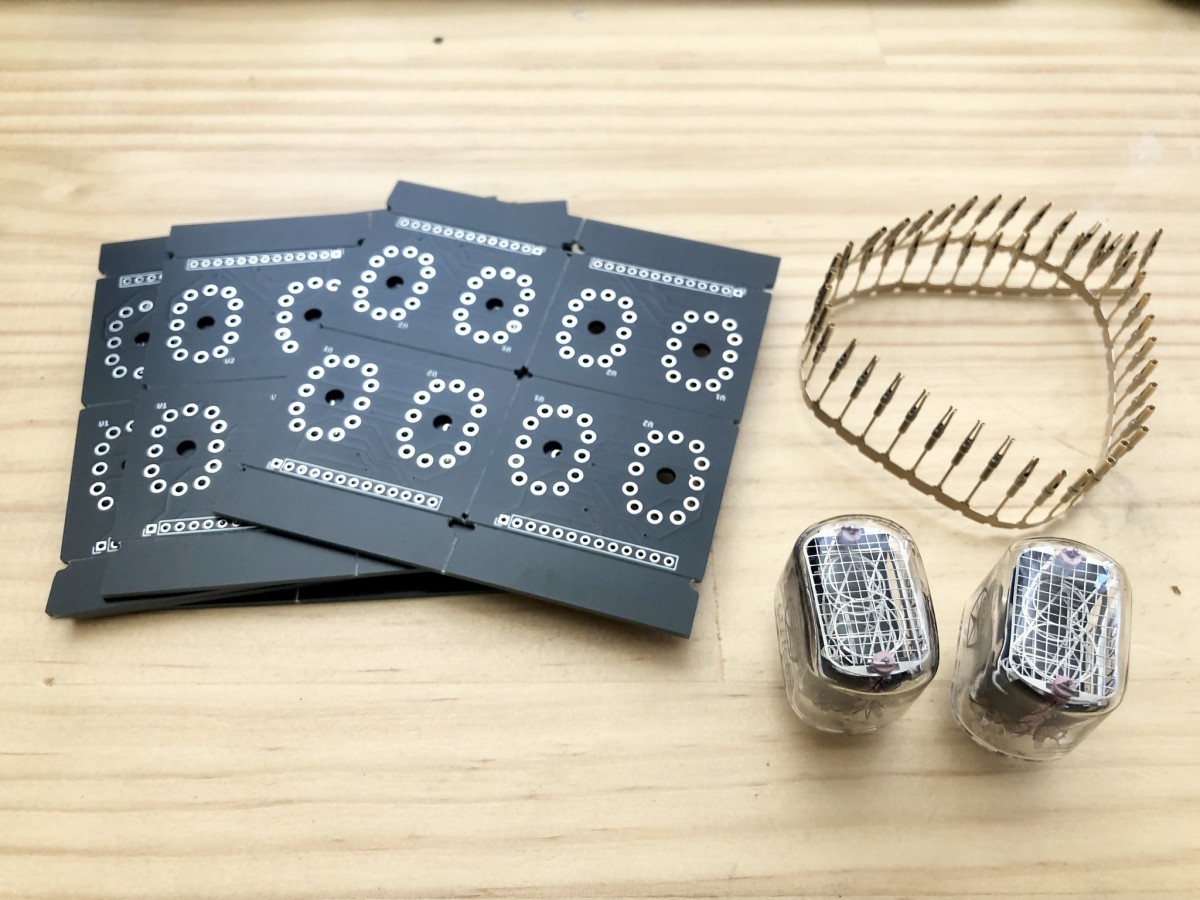
I made IN - 12B 2 digit board using JLCPCB. Since this is a test, I would like to use a socket instead of directly soldering the nixie tube to the board.
I bought this socket from Aliexpress.
 AliExpress.com Product - 1.0 Female Terminal Female Pin IN12 Socket IN18 QS30-1 QS27-1 YS27-3
This is also sold on Amazon.
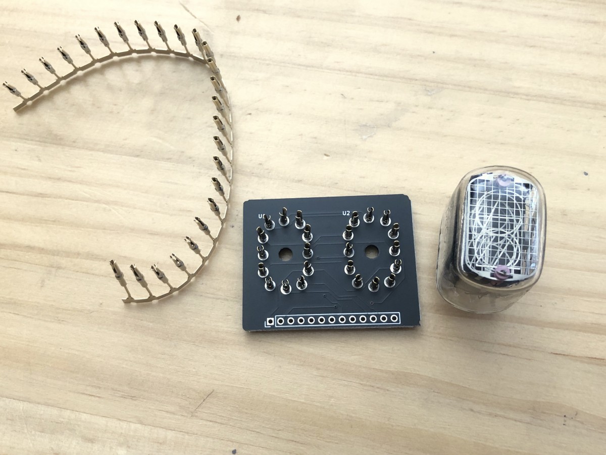
I attached a socket.
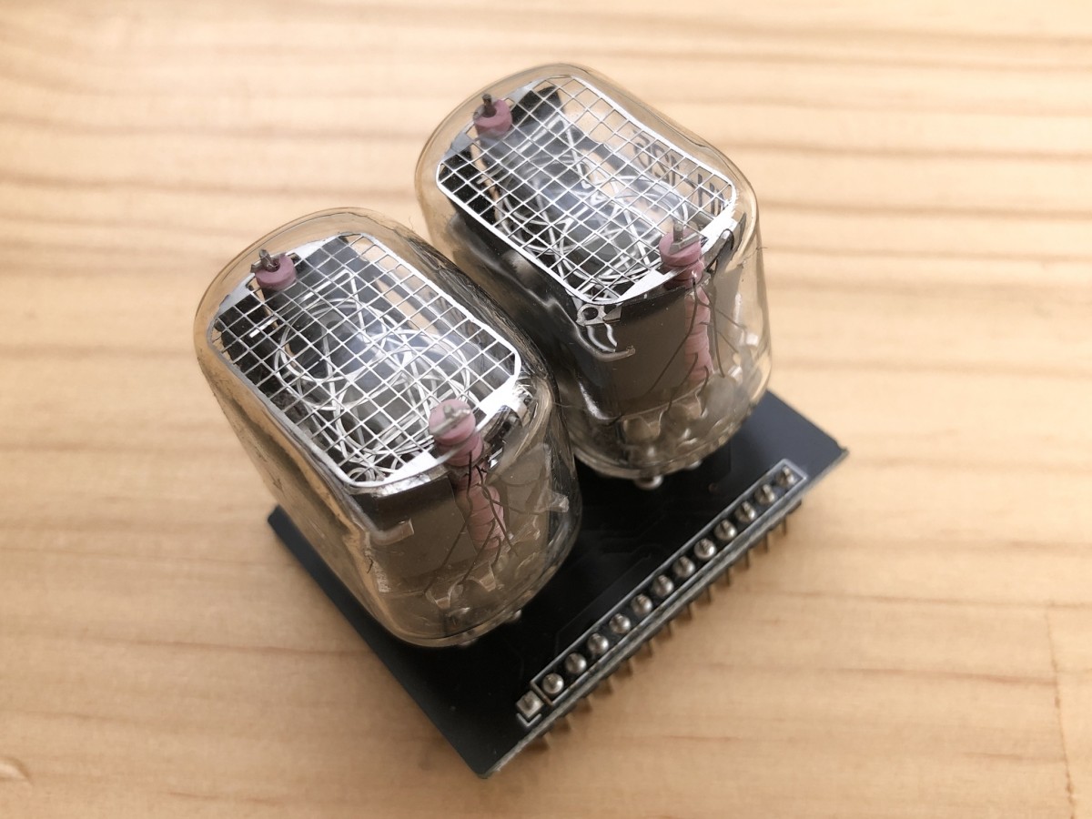
Attach the pin header to this and complete the board.
Controlling 1 digits with K155ID1
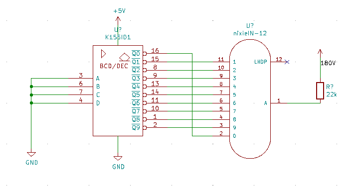
First of all, as a basic circuit, I would like to display 0 by connecting the nixie tube IN-12B and K155ID1.
Using ESP 32 to display from 0 to 9
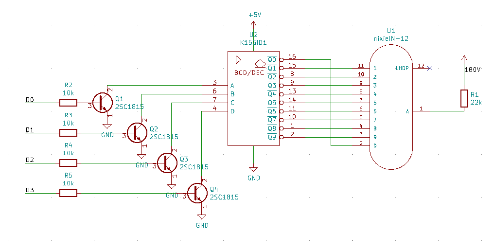
The output pin of ESP 32 is 3.3V. On the other hand, K155 ID1 has a TTL input of 5V. Since the voltage is different between the 3.3V system and the 5V system, a level conversion circuit was used. The level conversion is from the resistor to the transistor on the left side of the above circuit diagram. Since K1551 ID 1 is the TTL input, it is OK to pull out the current with the transistor instead of the push-pull.
However, the logic is reversed in this circuit. To specify K155 ID 1 as "0000", enter "1111", and to specify "0101", enter 1010 from D0 to D3.
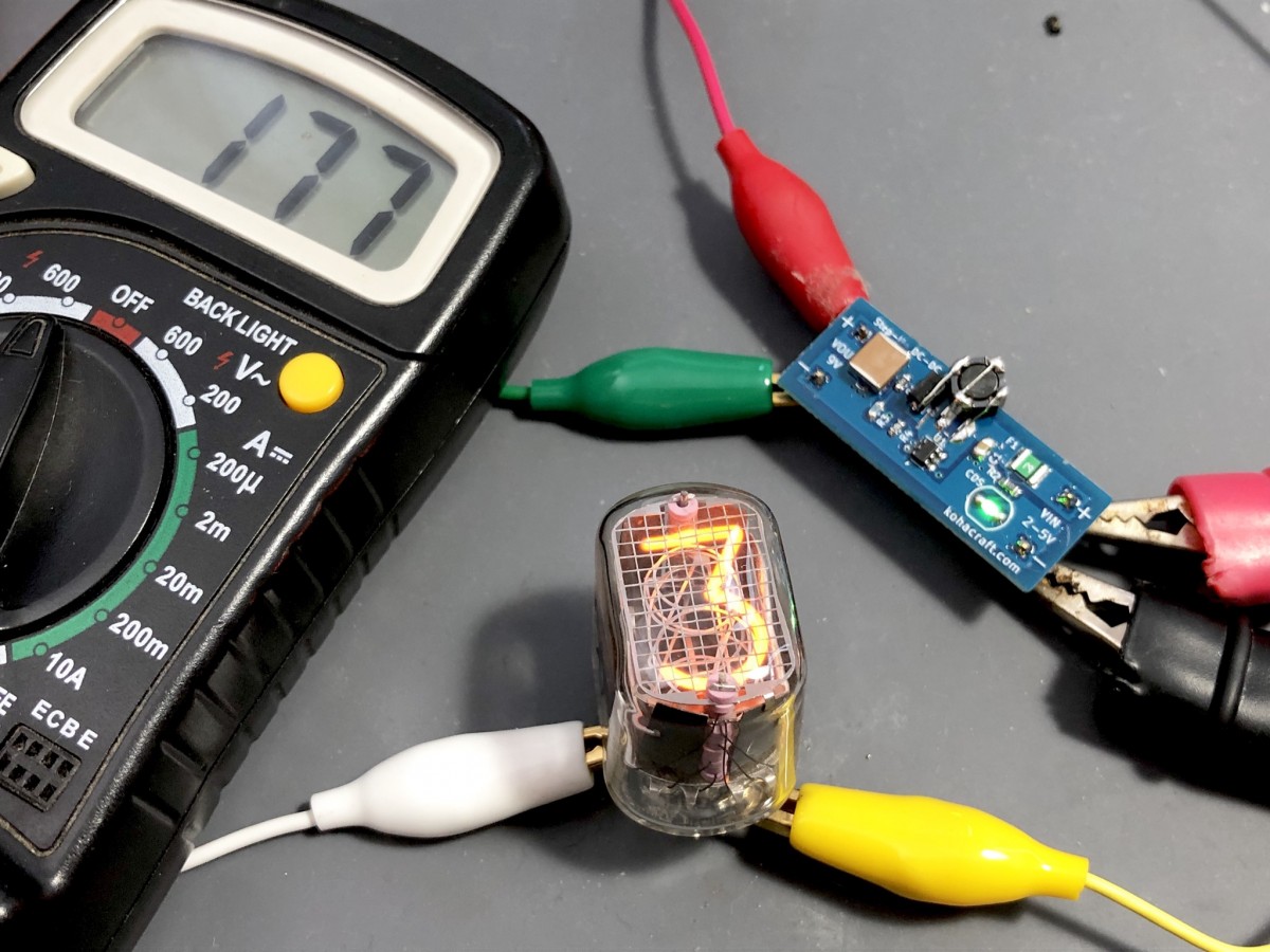
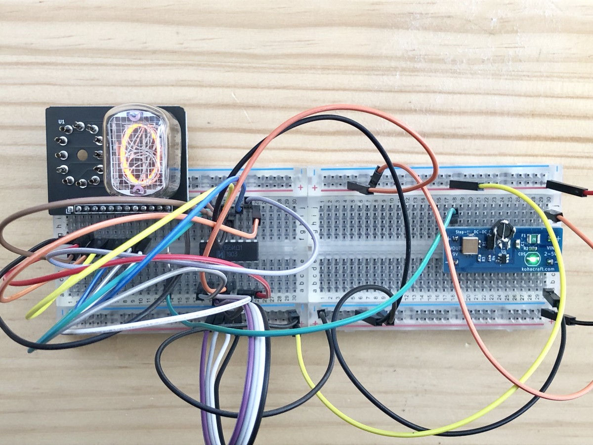
The display changes.
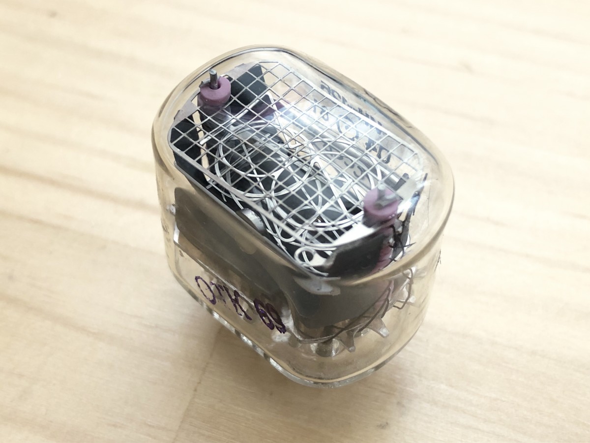
Let's look at the Nixie tube closer.
The light is also warm.
2 digits dynamic scan
In the past, only 1 orders of magnitude were illuminated, but next, 2 Nixie tubes are illuminated alternately at high speed, as if 2 were simultaneously illuminated.
Photocoupler
Turn ON and OFF 180V on the anode side of the nixie tube. You can make a switching circuit with transistors, but a popular method is to use a photocoupler.
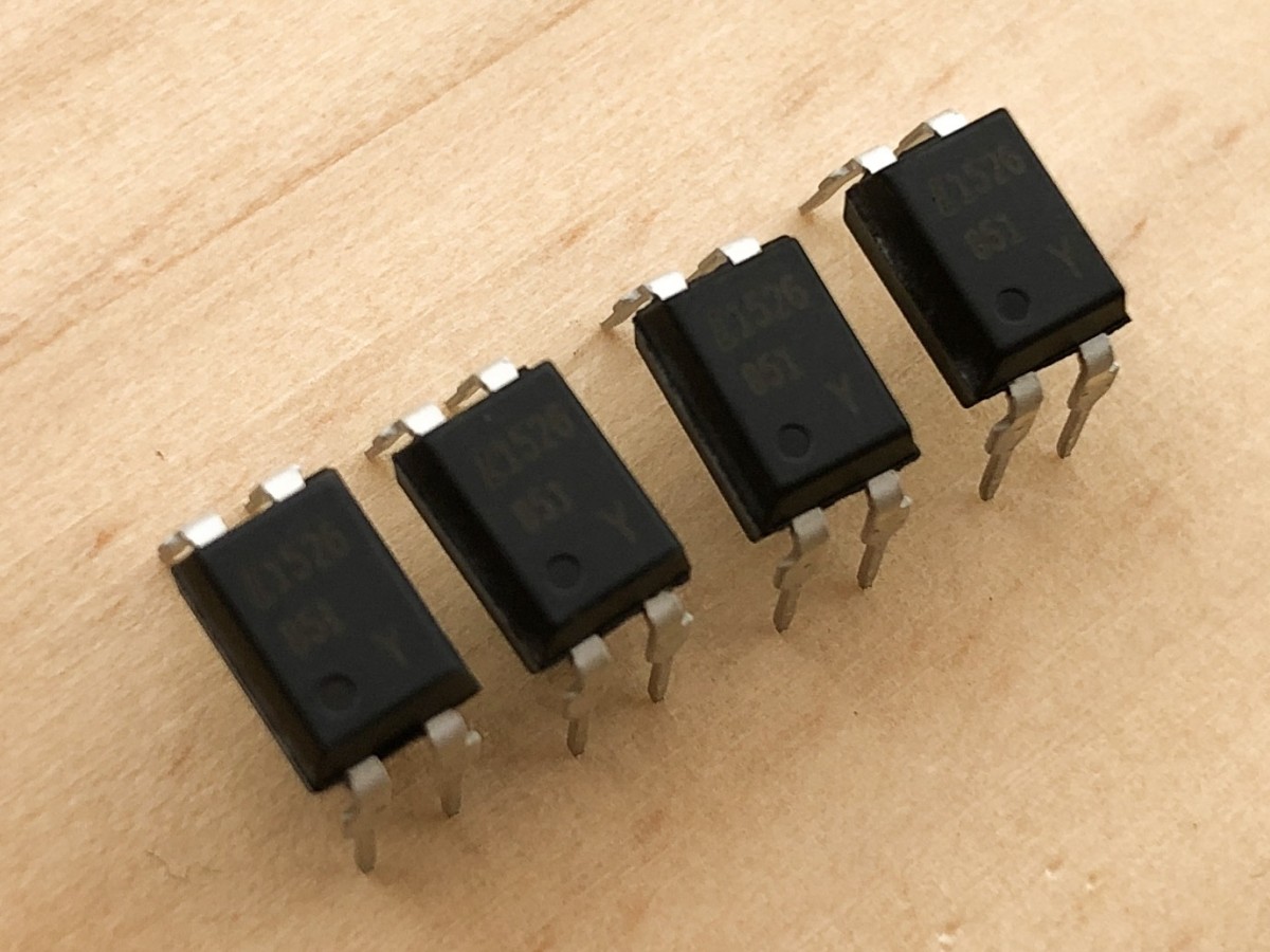
I chose LTV 851 because it was reasonable.
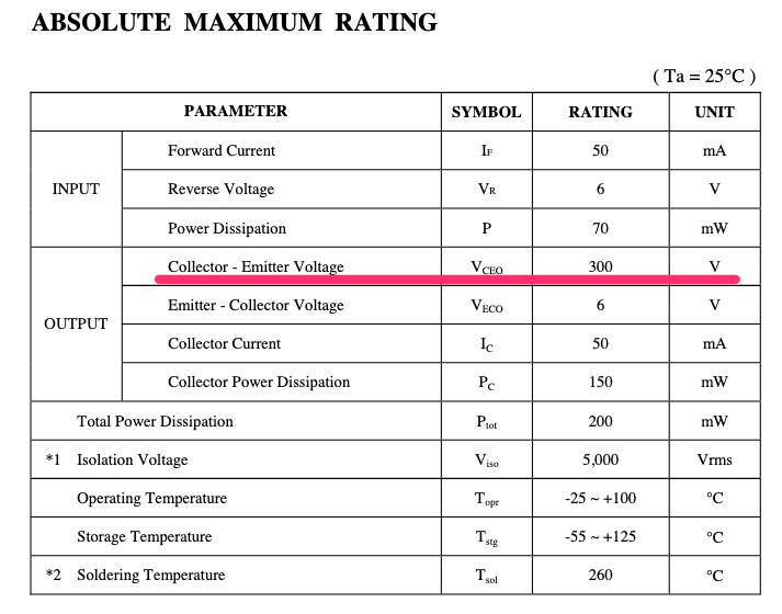
According to the data sheet, the collector-emitter voltage (VCEO) is 300V, which is sufficient for this application.
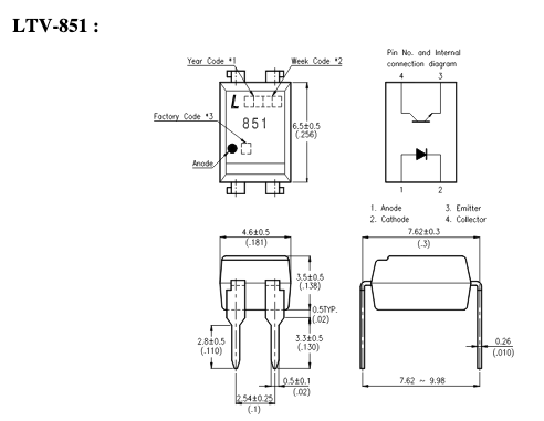
The photocoupler has a structure in which the LED and the phototransistor face each other. When the LED lights up, the phototransistor receiving the light turns on.
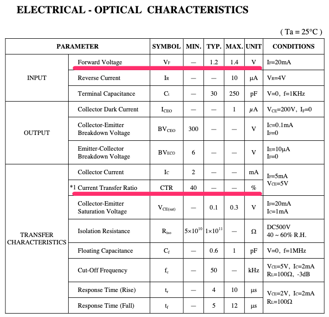
Calculate the resistance to allow the appropriate current to flow through the LED. In the photocoupler, the amount of current flowing through the transistor when the transistor is turned on changes according to the current flowing through the LED. You can see what the ratio is by looking at the Current Transfer Ratio (CTR) column.
40% means that if 1 mA is applied to the LED, 40% of that 0.4 mA will be applied to the transistor.
This time, since 2 mA is desired to flow in the nixie tube, it is necessary to flow more than 5 mA such as ILED = 2 mA / 40% = 2 mA / 0.4 = 5 mA.
Since the current flowing through the LED is determined, the resistance value of the resistor connected to the LED is obtained. The LED forward voltage is 1.4V maximum in the Forward Voltage column.
Assuming that the voltage when the pin of ESP 32 is turned on is 3.3V, the resistance value is
R = (3.3V - 1.4V) / 5 mA = 1.9V / 5 mA = 380 [Ω].
Therefore, the resistance connected to the LED should be 380 Ω or less, and the close value should be 330 Ω.
Circuit diagram
The constant of the photocoupler has been decided, so I will write a circuit diagram.
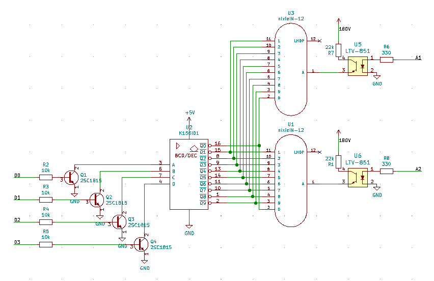
The schematic on the right side of the Nixie tube is where I added it.
By turning on 2 nixie tubes alternately, you should be able to display 2 digits.By turning on 2 nixie tubes alternately, you should be able to display 2 digits.
Programming
Here's a program for ESP 32 written in Arduino.
const int D0 = 26;
const int D1 = 25;
const int D2 = 33;
const int D3 = 32;

const int A1 = 14;
const int A2 = 27;

void setup() {
  pinMode( A1, OUTPUT );
  digitalWrite( A1, LOW );
  pinMode( A2, OUTPUT );
  digitalWrite( A2, LOW );

  pinMode( D0, OUTPUT );
  digitalWrite( D0, HIGH );
  pinMode( D1, OUTPUT );
  digitalWrite( D1, HIGH );
  pinMode( D2, OUTPUT );
  digitalWrite( D2, HIGH );
  pinMode( D3, OUTPUT );
  digitalWrite( D3, HIGH );
}

void numOut( int num )
{
  digitalWrite( D0, !( num & ( 1 << 0 ) ) != 0 );
  digitalWrite( D1, !( num & ( 1 << 1 ) ) != 0 );
  digitalWrite( D2, !( num & ( 1 << 2 ) ) != 0 );
  digitalWrite( D3, !( num & ( 1 << 3 ) ) != 0 );
}

void loop() {
  for ( int i = 0 ; i < 100 ; i++ )
  {
    for( int j=0 ; j<100 ; j++ )
    {
       //First digit display
      numOut( i%10 );
      digitalWrite( A1, HIGH );
      delay(1);
      digitalWrite( A1, LOW );
      delayMicroseconds(100); //less than 100 us, there will be afterimages.

      //Second digit display
      numOut( (i/10)%10 );
      digitalWrite( A2, HIGH );
      delay(1);
      digitalWrite( A2, LOW );
      delayMicroseconds(100); //Afterimage occurs below 100 us
    }
  }
}
This is a program that counts up from 00 to 99. The numOut () function converts a number between 0 and 9 to a K155ID1 2 digit.
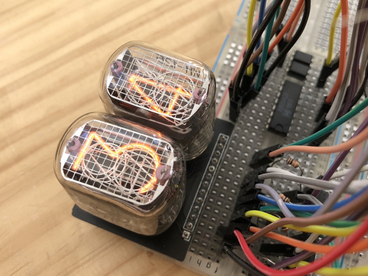
Let it work.
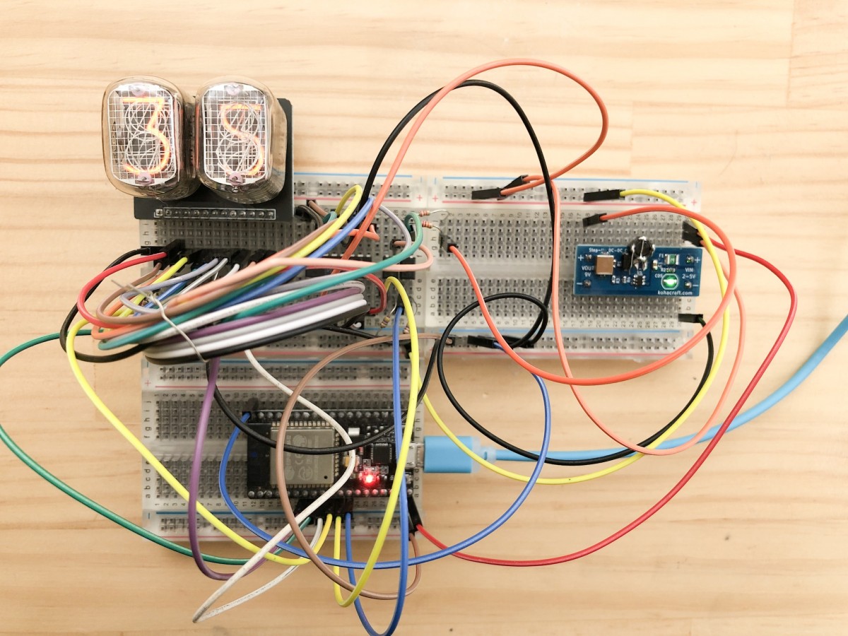
I could display 2 digits!
ESP 32 was able to turn on the 2 digit Nixie tube dynamically
By extending this mechanism, more Nixie tubes can be turned on.
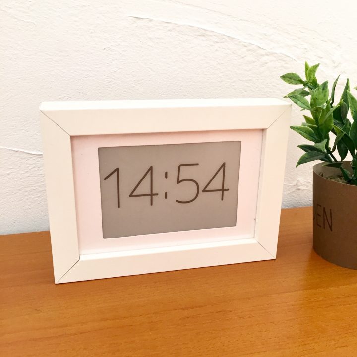
2019.11.22 Additional sequel here ↓ I made a watch

End of addition
Please check it out.