I lit up a VFD indicator tube IV-6 that I bartered with a retro indicator tube enthusiast in Ukraine.
Here are the details of the barter.

Specifications of the IV-6

The IV-6 is a display tube that can display 7 segments and dots. The data sheet is in Russian, so I translated it into Japanese using Google Camera.

- Heater voltage: 1V
- Anode segment voltage: 25V
- Grid voltage: 25V
This is what I found out.
For the principle of VFD display, the diagram by Noritake Ise Electronics Co.


Pins 8 and 9 are the front of the pin layout.
- Pins 7 and 8 are heaters
- Pin 9 is the grid
- 1-6,10,11 are segments
- Pin 12 is NC
As above.
- 1V to heater on pins 7 and 8
- 25V to grid on pin 9
- 1-6,10,11 is 25V to the segment
We can make it light up by
Wiring
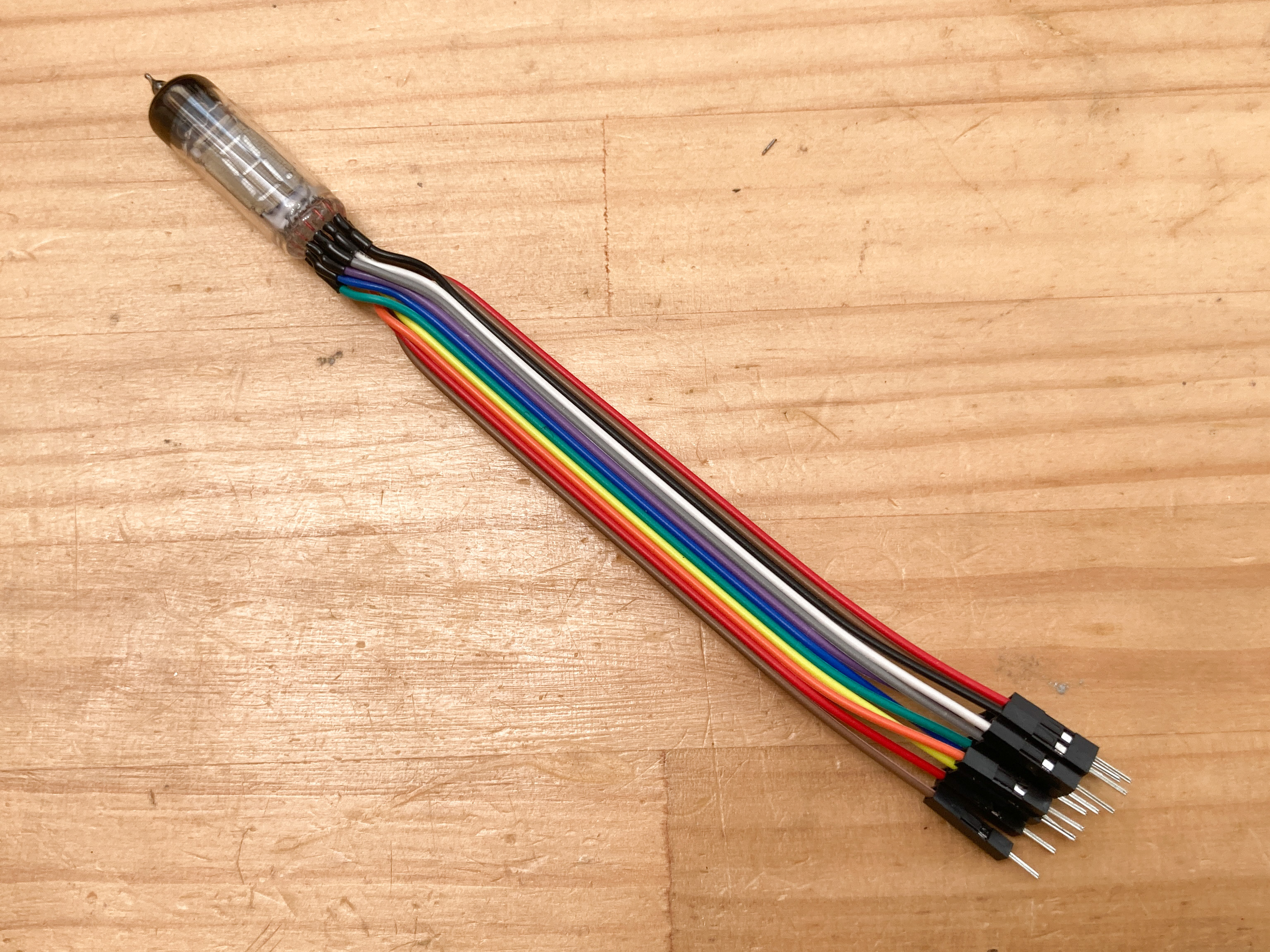
I have wired the jumper wires so that I can experiment with the breadboard.
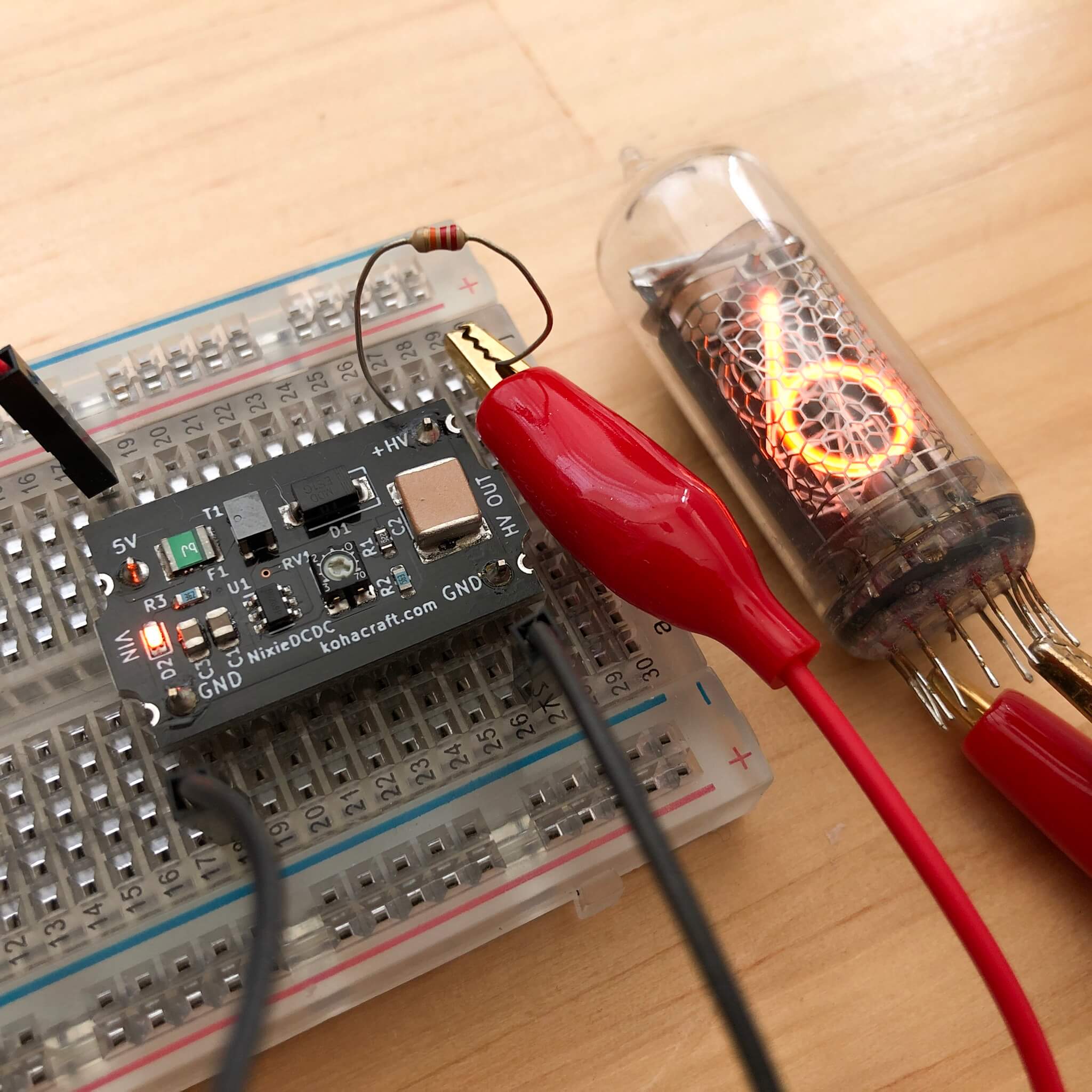
Applying voltage

We applied 1V to the heater and 25V to the grid and segments.

It glowed! It's a beautiful blue-white color.
Try to control it with ESP32
Circuit
 Since the voltage of VFD is about 25V, it is easier to control than Nixie tubes. This time, we will use Toshiba's TBD62783 as a driver IC to convert the 3.3V output of the ESP32 GPIO to 25V.
Program
This is a bit redundant, but I made it by appropriating the program for the clock of the display unit of Canon Canola L1211 that I made before.
//                        a   b   c   d  e   f   g  dp
const int SEG_PIN[8] = { 22, 23, 16, 17, 5, 18, 19, 4 };
const int SEG_NUM = 8;

//                            a  b  c  d  e  f  g
const bool CHAR[18][7] =   { {1, 1, 1, 1, 1, 1, 0}, {0, 1, 1, 0, 0, 0, 0}, {1, 1, 0, 1, 1, 0, 1}, {1, 1, 1, 1, 0, 0, 1},
  {0, 1, 1, 0, 0, 1, 1}, {1, 0, 1, 1, 0, 1, 1}, {1, 0, 1, 1, 1, 1, 1}, {1, 1, 1, 0, 0, 0, 0},
  {1, 1, 1, 1, 1, 1, 1}, {1, 1, 1, 1, 0, 1, 1}, {1, 1, 1, 0, 1, 1, 1}, {0, 0, 1, 1, 1, 1, 1},
  {1, 0, 0, 1, 1, 1, 0}, {0, 1, 1, 1, 1, 0, 1}, {1, 0, 0, 1, 1, 1, 1}, {1, 0, 0, 0, 1, 1, 1},
  {0, 0, 0, 0, 0, 0, 0}, {0, 0, 0, 0, 0, 0, 1}
};

#define DIGITS 1
#define SEGMENTS 7
bool dispString[DIGITS][SEGMENTS];

void setup() {
  //initialize GPIO
  for ( int i = 0 ; i < SEG_NUM ; i++)
  {
    pinMode(SEG_PIN[i], OUTPUT);
    digitalWrite(SEG_PIN[i], LOW);
  }
}

void loop() {
  int i = 0;
  for ( int j = 0 ; j < 10 ; j++ )
  {
    char str[2];
    sprintf( str , "%01d" , j );
    setChar( str[0] , i );
    digitalWrite(SEG_PIN[0], dispString[i][0]);
    digitalWrite(SEG_PIN[1], dispString[i][1]);
    digitalWrite(SEG_PIN[2], dispString[i][2]);
    digitalWrite(SEG_PIN[3], dispString[i][3]);
    digitalWrite(SEG_PIN[4], dispString[i][4]);
    digitalWrite(SEG_PIN[5], dispString[i][5]);
    digitalWrite(SEG_PIN[6], dispString[i][6]);
    digitalWrite(SEG_PIN[7], 0);
    delay(300);
  }
}

/********* function *********/
//set charactor pattern at digit
void setChar( char charctor , int digit )
{
  int id = 0;
  switch ( charctor ) {
    case '0':  id = 0; break;
    case '1':  id = 1; break;
    case '2':  id = 2; break;
    case '3':  id = 3; break;
    case '4':  id = 4; break;
    case '5':  id = 5; break;
    case '6':  id = 6; break;
    case '7':  id = 7; break;
    case '8':  id = 8; break;
    case '9':  id = 9; break;
    case 'A':  id = 10; break;
    case 'B':  id = 11; break;
    case 'C':  id = 12; break;
    case 'D':  id = 13; break;
    case 'E':  id = 14; break;
    case 'F':  id = 15; break;
    case ' ':  id = 16; break;
    case '-':  id = 17; break;
    default:   id = 16; break;
  }
  dispString[digit][0] = CHAR[id][0];
  dispString[digit][1] = CHAR[id][1];
  dispString[digit][2] = CHAR[id][2];
  dispString[digit][3] = CHAR[id][3];
  dispString[digit][4] = CHAR[id][4];
  dispString[digit][5] = CHAR[id][5];
  dispString[digit][6] = CHAR[id][6];
}
Power on!

The numbers are now displayed!

It's pretty good.

The VFD tube, like the Nixie tube, has a structure inside the tube, which is very attractive.
Now that I've got the VFD working, I'd like to move on to making the clock.