Hi, I'm kohanii.
I thought I could make an LED dot matrix this time, using a board I made in the past that could mount an 8×8 push switch.
PCB

I had a few pieces left over that I hadn't used.
I'll post an image of the PCB scanned in here.
 Click here for the high resolution version.
 Click here for the high resolution version.
I cut out the bottom right corner of the scanned image and traced it. Looking at the wiring, it looks like you can connect the LEDs as well.
The red lineis the surface andthe blue lineis the wiring on the back side.Yellowis the through-hole.

If I put an LED where I would normally mount the switch and a resistor where I would mount the diode, this PCB looks easy to use.
In this case, the circuit looks like this. (The schematic is wrong and the connectors are reversed left and right.)

LED
I used one before when I replaced the LED in the ring light for my phone.
There was a 2700K (bulb color) version of the same thing and I would like to use that.
It's a chip LED, which is just fine.
The resistance is a suitable 100-ohm chip resistor.
soldering
64 LEDs and 64 resistors.
Solder all of these by hand.
Apply plenty of flux to the area to be soldered.

. . .

I was able to solder two lines.

I'm sure it glows.
Two hours later.
. . .
. . .
. . .
. . .
. . .
. . .
. . .
Complete

I did it !
Light Diffusion and Separation
As you would expect, the LEDs are widely spaced, so it's hard to see them as they are.
So I used a 3D printer to create a separation between each dot and put copy paper on top to make it easier to see.
For now, I'm going to do a quick 3D design in Blender.

The next step is to slice it in Cura to convert it into data for the 3D printer.

I don't want to spend too much time on this, so I set the print speed to high.
It appears to take 4 hours and 44 minutes to print. It's kind of an ominous number.
Now all I have to do is wait for the 3D printer to finish printing.

The next day
It's out of print

Completed. Or rather, I finished it in my sleep.
I'm still sleepy. It's just after 9am.

Paste copy paper on the surface with glue.
Try to move it

Anyway, I connected it to an Arduino Nano that I found around.
If you look at this picture, there's something stuck in the breadboard, but I just didn't remove it, it's unrelated.
Connected to the left of the PCB is a transistor array (TBD62083APG) for scanning the rows (GND side of the LEDs).
It can now be controlled by the I/O power of the microcontroller.


Here's what the program looks like.
int x_pins[8] = {
  5, 6, 7, 8, 9, 10, 11, 12
};

int y_pins[8] = {
  A0, A1, A2, A3, A4, A5, 4, 3
};

void setup() {
  for (int i = 0; i < 8; i++) {
    pinMode(x_pins[i], OUTPUT);
  }
  for (int i = 0; i < 8; i++) {
    pinMode(y_pins[i], OUTPUT);
  }
}

uint8_t data[8] = {
  0b11001100,
  0b11011000,
  0b11110000,
  0b11110000,
  0b11011000,
  0b11001100,
  0b11000110,
  0b11000011,
};

void loop() {
  for (int wait = 0; wait < 5; wait++) {
    for (int y = 0; y < 8; y++) {
      for (int i = 0; i < 8; i++) {
        digitalWrite(y_pins[i], LOW);
      }
      for (int x = 0; x < 8; x++) {
        digitalWrite(x_pins[x], (data[y] >> (7 - x)) & 1);
      }
      digitalWrite(y_pins[y], HIGH);
      delayMicroseconds(1000);
      for (int i = 0; i < 8; i++) {
        digitalWrite(y_pins[i], LOW);
      }
    }
  }
  for (int y = 0; y < 8; y++) {
    uint32_t now = data[y];
    now |= (now << 8) | (now << 16);
    now <<= 1;
    data[y] = (now >> 8);
  }
}
Shiny!!!

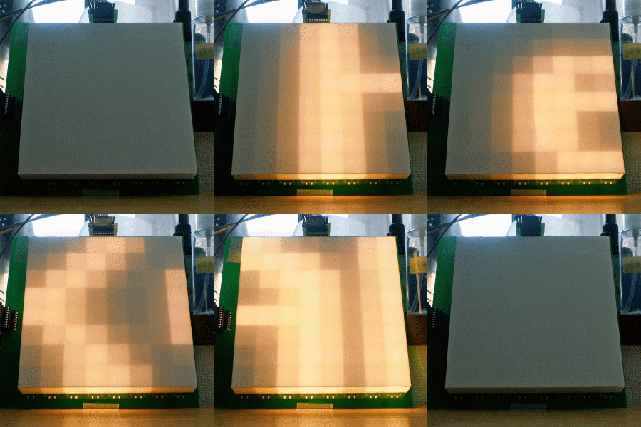
Something's moving! I can't see it!
Anyway, I'm going to cover the LED light diffuser and light blocker.

It's working!

The "K" is scrolling properly.
It is as programmed.

If we look at it from the side, you can see that the light is properly diffused inside.
I did it !!
The end


