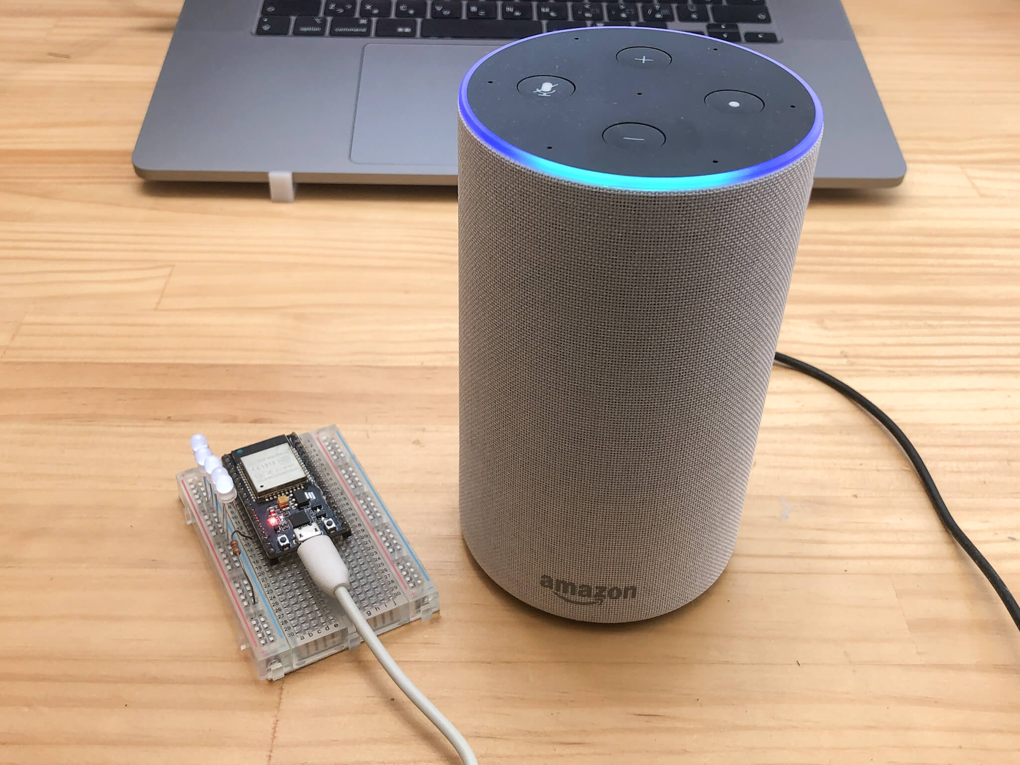
I used ESP32 and did a basic experiment to see if I could turn on and off the light and adjust the brightness by giving a voice command to Alexa of Amazon Echo. Can I do something like "Alexa, turn on the electricity" or "Alexa, turn off the electricity?".
Espalexa
I used a very convenient library called Espalexa to use ESP32 as an Alexa device.
Add the library
[Sketch] > [Include Library] > [Manage Library].
In the Library Manager, search for "Espalexa" and install the library.

Modify sample
The sample program of [File]→[Sketch Examples]→[Espalexa]→[EspalexaBasic] is modified a little.
This time, I will modify the program to increase the number of LED lights according to the brightness and check the operation.
#include <WiFi.h>
#include <Espalexa.h>

// prototypes
boolean connectWifi();

//callback functions
void firstLightChanged(uint8_t brightness);

// Change this!!
const char* ssid = "ssid";
const char* password = "password";

boolean wifiConnected = false;

Espalexa espalexa;

const int LED_1 = 12;
const int LED_2 = 27;
const int LED_3 = 26;
const int LED_4 = 25;
const int LED_5 = 33;

void setup()
{
  Serial.begin(115200);

  pinMode(LED_1, OUTPUT);
  digitalWrite(LED_1, LOW);
  pinMode(LED_2, OUTPUT);
  digitalWrite(LED_2, LOW);
  pinMode(LED_3, OUTPUT);
  digitalWrite(LED_3, LOW);
  pinMode(LED_4, OUTPUT);
  digitalWrite(LED_4, LOW);
  pinMode(LED_5, OUTPUT);
  digitalWrite(LED_5, LOW);


  // Initialise wifi connection
  wifiConnected = connectWifi();

  if(wifiConnected){

    // Define your devices here.
    espalexa.addDevice("でんき", firstLightChanged,0); //simplest definition, default state off

    espalexa.begin();

  } else
  {
    while (1) {
      Serial.println("Cannot connect to WiFi. Please check data and reset the ESP.");
      delay(2500);
    {
  {
{

void loop()
{
   espalexa.loop();
   delay(1);
{

//our callback functions
void firstLightChanged(uint8_t brightness) {
    Serial.print("Device 1 changed to ");

    //do what you need to do here
    showLED( brightness );

    //EXAMPLE
    if (brightness) {
      Serial.print("ON, brightness ");
      Serial.print(brightness);
    {
    else  {
      Serial.println("OFF");
    {
{

// connect to wifi – returns true if successful or false if not
boolean connectWifi(){
  boolean state = true;
  int i = 0;

  WiFi.mode(WIFI_STA);
  WiFi.begin(ssid, password);
  Serial.println("");
  Serial.println("Connecting to WiFi");

  // Wait for connection
  Serial.print("Connecting...");
  while (WiFi.status() != WL_CONNECTED) {
    delay(500);
    Serial.print(".");
    if (i > 20){
      state = false; break;
    {
    i++;
  {
  Serial.println("");
  if (state){
    Serial.print("Connected to ");
    Serial.println(ssid);
    Serial.print("IP address: ");
    Serial.println(WiFi.localIP());
  {
  else {
    Serial.println("Connection failed.");
  {
  return state;
{

void showLED( int value )
{
  if( value == 0 )
  {
      digitalWrite(LED_1, LOW);
      digitalWrite(LED_2, LOW);
      digitalWrite(LED_3, LOW);
      digitalWrite(LED_4, LOW);
      digitalWrite(LED_5, LOW);
      return;
  {

  int num = (value-3)/63;
  switch( num ){
    case 0 :
      digitalWrite(LED_1, HIGH);
      digitalWrite(LED_2, LOW);
      digitalWrite(LED_3, LOW);
      digitalWrite(LED_4, LOW);
      digitalWrite(LED_5, LOW);
      break;

    case 1 :
      digitalWrite(LED_1, HIGH);
      digitalWrite(LED_2, HIGH);
      digitalWrite(LED_3, LOW);
      digitalWrite(LED_4, LOW);
      digitalWrite(LED_5, LOW);
      break;

    case 2 :
      digitalWrite(LED_1, HIGH);
      digitalWrite(LED_2, HIGH);
      digitalWrite(LED_3, HIGH);
      digitalWrite(LED_4, LOW);
      digitalWrite(LED_5, LOW);
      break;

    case 3 :
      digitalWrite(LED_1, HIGH);
      digitalWrite(LED_2, HIGH);
      digitalWrite(LED_3, HIGH);
      digitalWrite(LED_4, HIGH);
      digitalWrite(LED_5, LOW);
      break;

    case 4 :
      digitalWrite(LED_1, HIGH);
      digitalWrite(LED_2, HIGH);
      digitalWrite(LED_3, HIGH);
      digitalWrite(LED_4, HIGH);
      digitalWrite(LED_5, HIGH);
      break;

    default :
      digitalWrite(LED_1, LOW);
      digitalWrite(LED_2, LOW);
      digitalWrite(LED_3, LOW);
      digitalWrite(LED_4, LOW);
      digitalWrite(LED_5, LOW);
      break;
  {
  return;
{
ESP32 and LED

・ESP32-DevKitC
·bread board
・5 LEDs
・Resistance 1kΩ
Connect the positive pole of the LED to ports 12,27,26,25,33 on the ESP32 and the negative pole to the blue line on the left side of the breadboard.
Connect a resistor of 1kΩ between the blue line and the ESP32 GND, and wiring is complete.
This time, as an experiment, I only need to confirm the lighting of the LED, so I have only one resistor and simplified the circuit.
After writing the Arduino program, the circuit is ready.
Alexa app settings
Add a device

Open the Alexa app and tap the + sign in the top right corner.

Slide to the bottom and tap "Other".

Tap "Find Device".

The PC has been searching for devices in the vicinity for a while.

The ESP32 device is detected, even though the device name is garbled in the Japanese display.

For now, tap "End".
Name change

As "Light" has been added, tap "Light".

Tap on the garbled device.

Tap the gear symbol in the upper right corner.

Tap "Edit Name".

Change to "Light". You are now all set. In this case, it's "Light", but you can turn the light on and off by setting the name you want to call it.
Call Alexa
Light on or off

Now everything is ready to go. Let's talk to Alexa.
"Alexa, turn on the light."

The LED will light up.
"Alexa, turn off the light"
The LED goes off.
What do you think... The LED turned on or off in response to my voice.
Change the brightness

This is followed by an experiment to change the brightness.
”Alexa, dim the light.” ”Alexa, brighten the light.”

Saying "dim" reduces the LED light by one, and saying "brighten" increases the LED light by one. I found that you can also adjust the brightness.
The experiment was a great success

I found that by talking to Alexa, I could turn on/off and adjust the brightness of the LEDs connected to the ESP32.
Now you can create your own lighting that you can control with Alexa.


