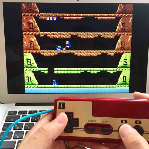
The Famicom can not connect to the TV.
So let's modify it to be able to output video and audio.
Clear video output
The NES uses an RF circuit to convert the video signal from the PPU and the audio signal from the CPU into an RF signal before outputting it. Therefore, the video signal from the PPU can be intercepted and routed through a video amplifier to produce a normal video output.
As I noticed when I saw the waveform, the video signal from the PPU of the Famicom has a slightly distorted waveform.
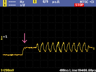
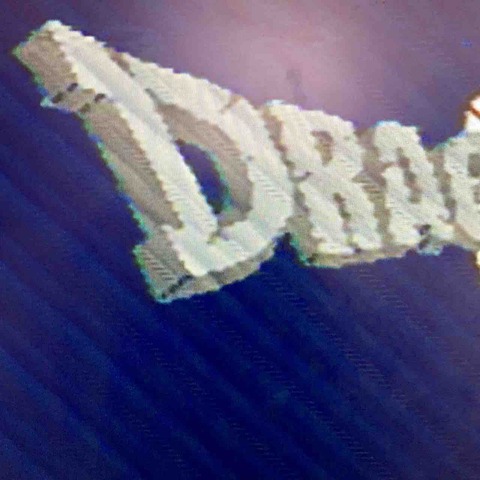
Like this, the part that should be sharp is dull and round. That means the image is also dull.
So I tried to compensate by filtering the curled part with the following circuit.
Famicom PPU---Circuit---Amplifier 6dp→Video output

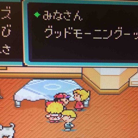
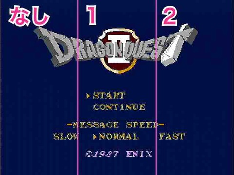
Let's see the difference in the video of Dragon Quest II.

Think of 0 pf as a normal image that does nothing. The larger the number, the more distinct the outline becomes. 20 pf is just right. 44 pf is a bit overcorrected.
I named this filtered video output circuit a "Clear video output circuit".
You can learn more about this experiment.

Nice stereo sound output
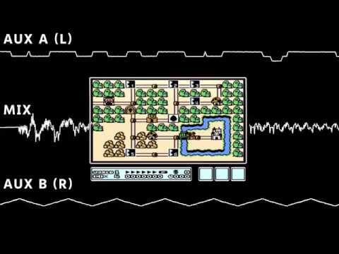
The sound of the Famicom is monaural. However, if you look closely at the circuit, the Famicom CPU has 2 sound outputs. Pin 1 of the CPU is called AUX A, and pin 2 is called AUX B. The difference is in the sound source.

These sounds are mixed in the Famicom circuit and are output as mono. Without mixing these outputs, AUX A is the left channel and AUX B is the right channel. The left speaker produces the Famicom characteristic electronic sound, and the right speaker produces the sound of the bass and drums. This is how the sound is heard.
Read more about stereo experiments.

By assigning the sound source to the left and right channels, it looks like stereo, but I get tired when I hear a completely different sound on the left and right. So I tried to improve it to a natural stereo signal by mixing the left sound slightly to the right and the right sound slightly to the left. The circuit looks like this.

↓2020.2.5 Added
Including the amplifier circuit, the circuit diagram looks like this.

↑2020.2.5 Added.
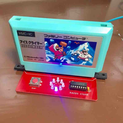
Make a circuits at the RF substrate size


The original board is replaced with a new board and wiring is completed. A 10 uF ceramic capacitor is attached to the main board to protect against vertical and diagonal stripe noise. Details of the stripe protection are shown here.
Very nice.
What I found when I tried is that the regulator generates a lot of heat, and the sound signal contains noise to match the image.
As a measure against heat generation, it is necessary to release heat firmly. The regulator of the RF board that is originally attached have a heat sink made of aluminum shield. It needs something like a heat sink.
 ebay.com