I want an Alexa-enabled ceiling light
When I go to bed at night, I use the remote control because I can't be bothered to turn the lights off with the wall switch. But sometimes I can't find the remote control for the lights.
I was tempted to use Alexa on my Amazon Echo to turn the ceiling lights on and off with my voice, since it's a pain to find the remote control.
Already, an Alexa-compatible ceiling light is available from "Iris Ohyama". But I would like to make it by myself.
Make a ceiling light with LED fluorescent lamps from Daiso
Previously, I modified an ordinary fluorescent ceiling light to LED ceiling light using LED fluorescent lamps from Daiso.
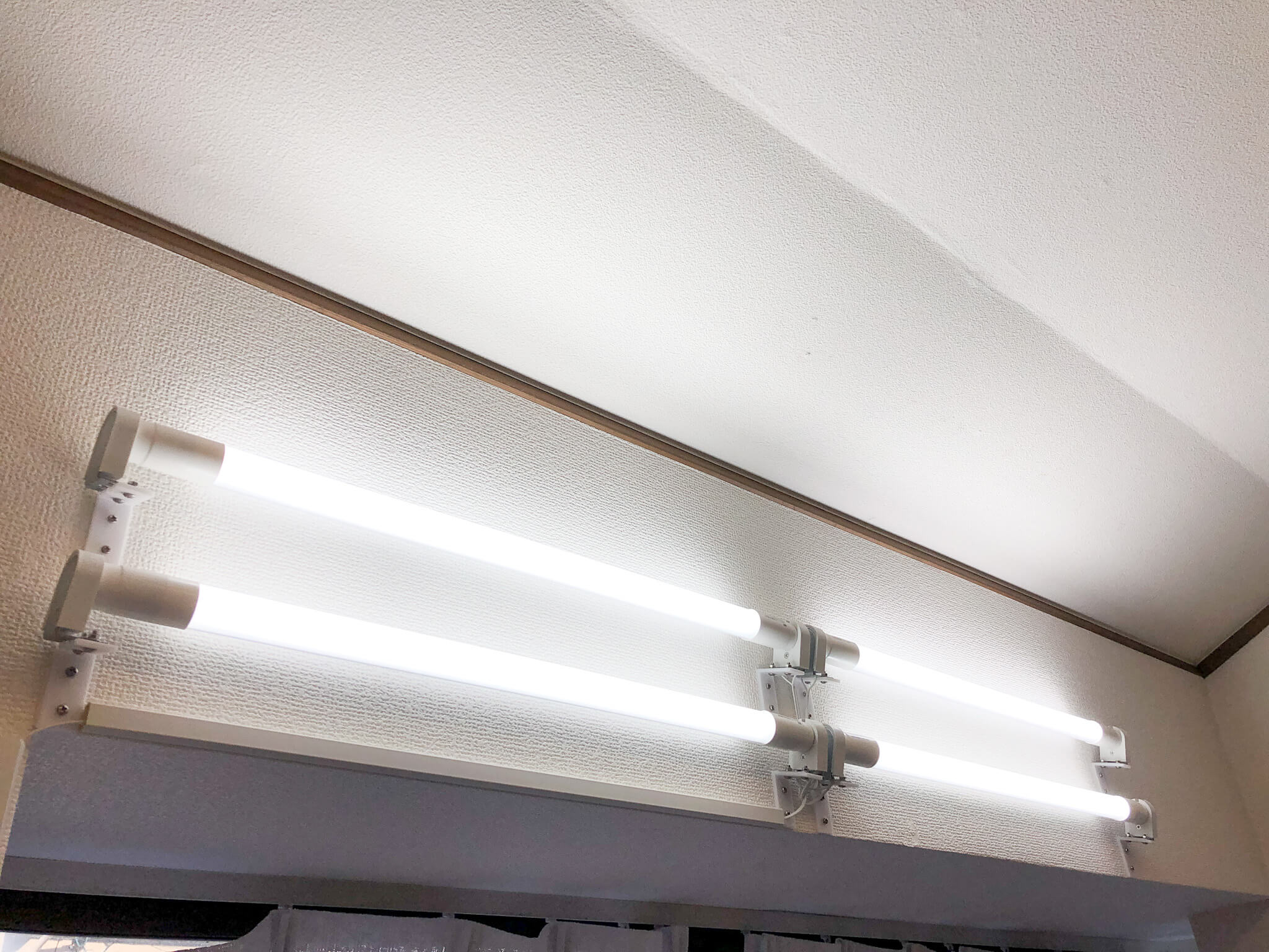
Again, I would like to modify an old fluorescent ceiling light in the room to LED with LED fluorescent lights from Daiso.
Receive Alexa's instructions on ESP32
In the previous experiment, I connected ESP32 to Amazon Echo via wireless LAN.
Then, using Alexa, the LED turned on when I said "Turn on the electricity" and the LED turned off when I said "Turn off the electricity".
It has also been found that you can adjust the brightness by instructing "Alexa, dim the lights" or "Alexa, brighten the lights".
So, in addition to ON, OFF, I'd also like to incorporate a brightness adjustment function.
Adjusting the Brightness of LED Fluorescent Light Bulbs from Daiso
After examining the circuit of the LED fluorescent lamp of Daiso, I found that the brightness of the LED can be adjusted by changing the resistance value.
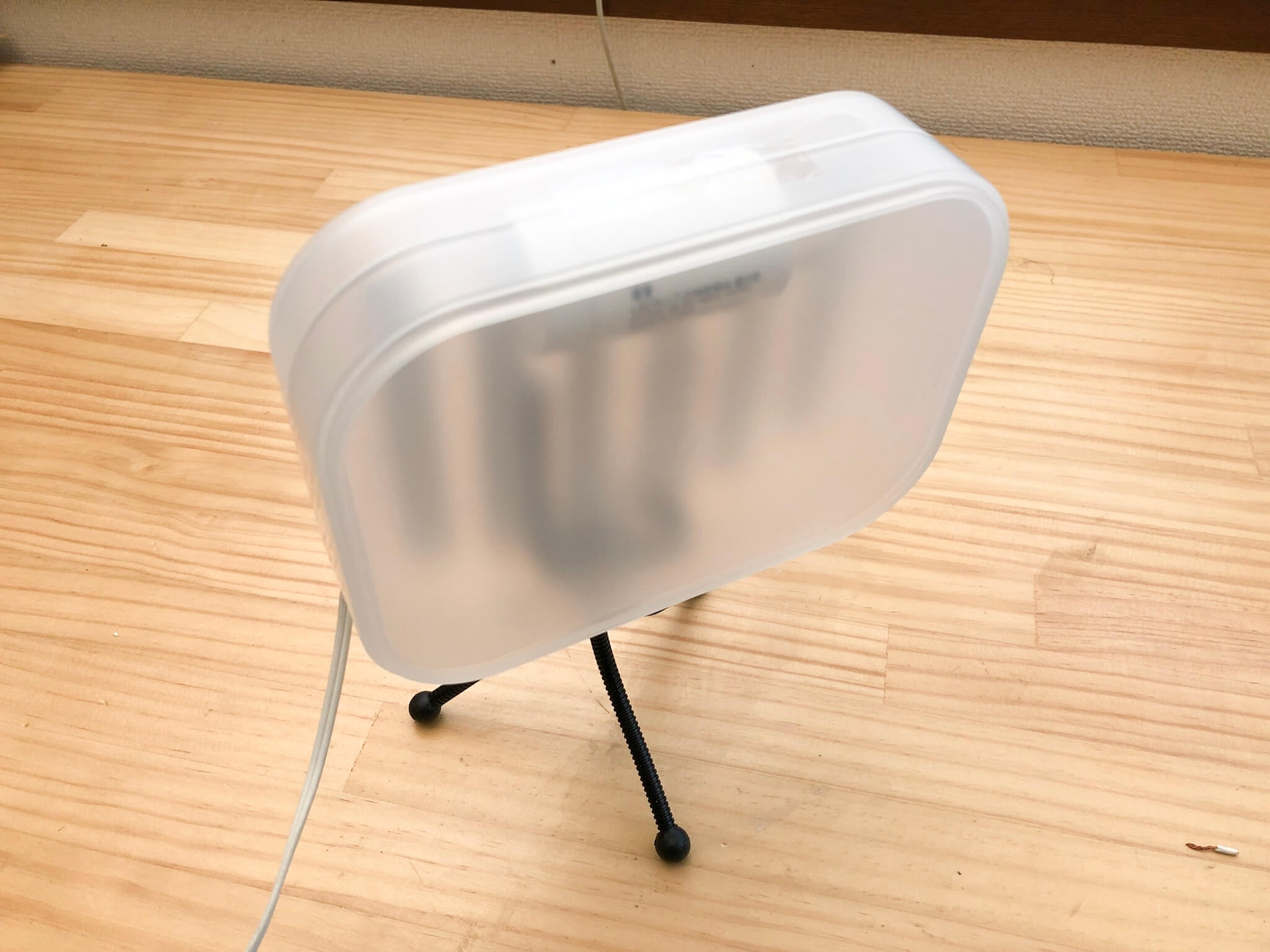
I actually modified the lighting for the photo shoot made from LED fluorescent lamps from Daiso so that we can use the volume to adjust the brightness.
Turning on, off and dimming LED fluorescent lamps from Daiso with ESP32
In previous experiments,
- ESP32 accepts lighting ON/OFF instructions from Alexa
- Adjust the brightness of Daiso's LED fluorescent
Each of the above individual functions has been realized.
Therefore, we would like to combine these to create a ceiling light with a dimming function that is compatible with Alexa.
Block diagram
The above diagram is a block diagram of the Alexa-compatible ceiling light we will create. Use ES32-DevKitC for ESP32. The ESP32 turns the LED fluorescent lamp on and off (switch section) and gives dimming instructions (dimmer section).
Since one LED fluorescent light is not enough as room lighting, I decided to use two.
All controls from the ESP32 to the switch and dimmer section are electrically isolated. This is because the GND potential of the ESP32 and the GND potential of the LED fluorescent lamp are completely separate, so if you make them common, an overcurrent will probably flow and the lamp will burn. It is always insulated.
ON,OFF(switch)of LED fluorescent lamp
Use the Solid State Relay (SSR) AQH2213 to turn on and off the AC power. This solid-state relay is a semiconductor type AC power supply relay in which the control part and switch sections isolated by light. To control it, you only need to turn on and off the built-in LEDs, so it can be controlled with less power than ordinary relays, which is ideal for control by a microcontroller.
The AQH2213 also has a function called zero cross that turns it on and off when the AC voltage is 0V. Since it turns on and off at 0V, there is an advantage that noise does not appear easily when turning on and off.
By connecting as shown in the figure above, it works as a relay.
Calculating resistance
The SSR is controlled by lighting the LED built into the SSR with ESP32. However, if you directly connect the output pin of the ESP32 and the LED of the SSR, an overcurrent will flow and it will be destroyed. Therefore, a current limiting resistor is placed between the output pin and the LED of SSR. This is the RIN in the connection diagram I mentioned earlier. This resistance value is calculated.
According to the datasheet, the LED only needs to flow 20mA and the voltage of the LED is 1.3V at that time. If the voltage at the output pin of ESP32 is 3V, the resistance of the limiting resistor is...
RIN = ( 3V - 1.3V ) / 20mA = 85Ω
It goes like this. Let ”RIN = 82Ω” as a value that the resistor is readily available.
Dimming instructions (Dimmer section)
The circuit of Daiso's LED fluorescent lamp is as shown above. The LED current can be adjusted by changing the resistance value connected to the CS pin of the IC. In the circuit of Daiso's LED fluorescent lamp, it is 2.1Ω. By increasing this resistance value, the LED current decreases and the light can be dim.
In order to adjust this resistance from ESP32, modify the circuit as shown in the figure below.
Connect three sets of resistors and switches in parallel (S1, S2, S3) and then connect more resistors in parallel. The resistance value is shown in the figure. With this kind of circuit, when each switch is turned on and off, the value of the composite resistance changes in steps from 16Ω to 2Ω.
The current flowing through the resistor can be varied from 37.5 mA to 300 mA in steps of 37.5 mA each, according to the simulation.
The above mechanism is used to dimmer the LED fluorescent light from Daiso.
Switch design
Since the mechanism has been decided, we will design the switch. When controlling the switch from the microcomputer, it must be electrically isolated. Therefore, I decided to use Photomos relay.
PhotoMOS relay is a semiconductor type relay that is insulated by light. Although the SSR used earlier is exclusively for AC, the PhotoMOS relay can also be used to turn DC on and off.
I decided to use the AQY221, which is a very small photoMOS relay with a maximum resistance value of 0.5Ω when it is ON.
Limiting resistor design
The switch can be controlled by turning on and off the LED built into the photomos relay, but to control with the microcomputer, the current limiting resistor is required, just as in the case of SSR.
According to the data sheet, the maximum value of operating LED current is 3mA, so the current should be 5mA with a margin. The maximum LED voltage drop is 1.5 V. If the voltage when the output pin of the microcomputer is ON and 3V, the limiting resistance R is
R = ( 3V - 1.5V ) / 5mA = 300Ω
The resistor is set to 270Ω, which is a value that the resistor is readily available.
Circuit diagram of light control section
I made a circuit diagram of the parameters so far. By adding this circuit to the circuit of the LED fluorescent lamp, it becomes possible to adjust the LED current stepwise by the microcomputer.
Creating a circuit
It's a very simple circuit because it's just ESP32-DevKitC, SSR, photo-mos relay and resistors.
Check the operation of the LED fluorescent lamp ON and OFF (switch section)
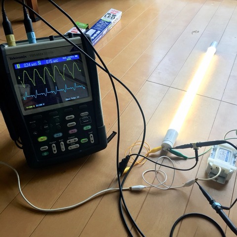
The signal from the microcontroller showed that the SSR turns on and the voltage goes to 100V. Test to see if it shines when connected to an LED fluorescent lamp.
The LED fluorescent lamp has been successfully turned on and off. The switch section worked properly.
Modify LED Fluorescent Lamps
Disassembles the Daiso LED fluorescent lamp. We will modify the brown PCB connected to the LED PCB.
Remove the two resistors on the back of this PCB.
Wire the circuit of the dimming part to the place where the removed resistance was.
Now let's test if dimming is possible.
Dimming also worked properly.
Completing the circuit
Complete the circuit by wiring the two LED fluorescent lights and adding a surge absorber as a protection circuit to the power supply.
Now that the hardware is complete, We'll make the software next time.


