Canola L1211
 The Canola L1211 was a desktop calculator sold by Canon in the 1970s. It is connected to an electrical outlet and has an orange indicator.

It is round and shaped like a typewriter.

This calculator is quite old, so it often runs out of control and does not work properly.
Let's open the inside
The state inside

It can be easily opened by removing the four screws.

There was a stamp that said July 17, 1974. So this calculator was made in 1974.

This is the main board. It contains two large LSIs.

Here is the switch PCB.

This switch is not a regular mechanical key, but a magnetic sensor switch using a magnet and a reed switch.
Photo of the PCB
I'll post a picture of the PCB for you.
Main Board


I measured each voltage.
- VDD:-10V
- VGG:-17V
- VHI:213V
- H2:73V
- H3:157V
- VM:-24V
- VE:-7V
I thought the LSI was operating at 5V or some other positive voltage, but it seems to be operating at -10V or some other negative voltage. VHI, H2, H3 and 73V to 213V are used for the indicator system, but the rest of the voltage is negative.
Switch PCB

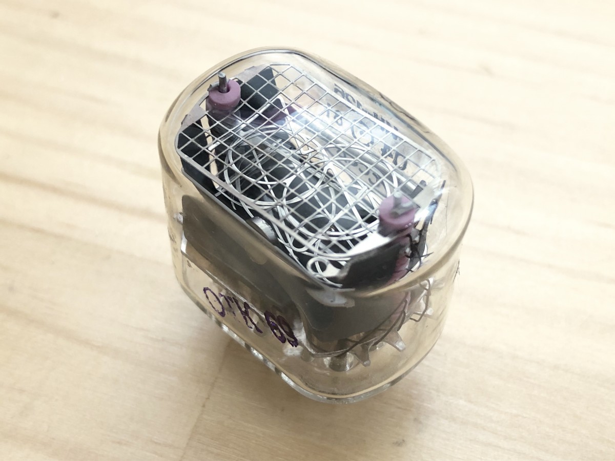
Indicator
View from the outside
The display unit used was a JRC (Japan Radio Co., Ltd.) SEPTANIX J4923A. It is a socket type and can be easily removed.


For more information on indicators of this age, please see this page.

It seems to be an indicator that was developed after the Nixie tube and used only for a short period of time before the VFD came along later.
How to light it
You can read more about it in Hitachi's Linestar H1833B document, which was developed at the same time.

Basically, it seems to be lit in the same way as a Nixie tube. Apply about 200V to the anode electrode of each digit, and connect the cathode of each segment to GND across a resistor of about 50kΩ, and the segment will light up.
To prevent the OFF segment from lighting up during dynamic lighting, a pre-bias, about half of the voltage of the anode electrode, is applied to the cathode with a 500kΩ resistor (Epb2).
Wiring

The pitch of the terminals of this indicator is 4mm, and this connector is not currently sold. So, I wired each electrode to a pin header so that I could stick it on the breadboard.

Now that I was able to stick it into the breadboard, I looked up the pinouts to see which pins were connected to where.
Pin assignment
Let's assume that the rightmost digit is A0, and the number gets larger as you move to the left.

Name each of the seven segments, dot, ', etc., as follows. The names of DP, COM, S1, and S2 are the ones written on the Calona1211 PCB.

Each pin assignment was as follows.

In the case of Leinster, the leftmost NC is a pin called Keep Alive, but JRC's septics were not connected to anything.
Let's light it up
I used the NixeDCDC, which is also used for Nixie tube clocks, as the power supply to generate the high voltage, and applied 180V.

Connect 180V to A1, 220kΩ to abcdefg, 470kΩ to DP and COM, and connect to GND.

It glowed! The color is like a Nixie tube.
For the Canola1211 board, the anode voltage was 213 V and the resistance of each segment of the cathode was 68 kΩ. This time, the anode voltage was 180V, and the resistance of each segment was 220kΩ, so the current flowing was small, but it turned out to glow properly. The current for each segment was 0.22mA. According to Leinster's documentation, it seems to be running at about 1mA to 1.5mA, so it might be OK to raise it a little more.
I was able to make it light up only one digit, and I will add a circuit to make it light up dynamically.
Added on April 10, 2021 Click here to continue.
End of addition