Here's how to use FCAV to convert your Nintendo Famicom (NES Japan Version) to video output in a super easy way.

The FCAV has the merit of reducing the vertical stripe noise inherent to the Nintendo Famicom as much as possible and allowing you to enjoy natural stereo sound when using the original modification method, but it can be a little difficult to modify. In this article, we will introduce a simple modification method that can be done even by a beginner solderer, although it will reduce the vertical stripe noise to a certain extent and the audio will be monaural as it was originally.
The original modification method is here.

Tools required for the work
Here are the tools needed for the modification.Phillips screwdriver
- Phillips screwdriver
- Soldering iron
- Solder
- Desoldering wire (not necessary)
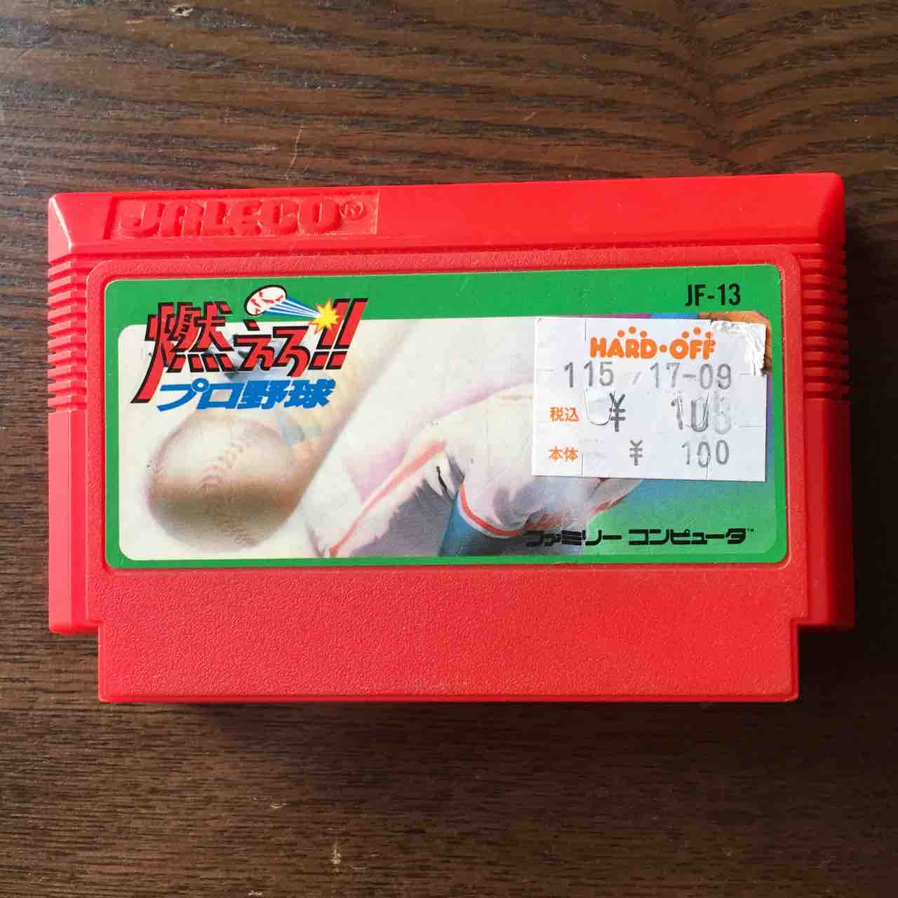
- Famicom (early model)
This is what the desoldering wire looks like.

Early model Famicom

There are two types of Famicom: early model and late model. The modifications introduced here are for the early model. To distinguish between early and late models, look at the connector where the cassette is inserted. If the connector is blue, it is an early model. If it is surrounded by silver metal, it is a late model.
For other detailed information on how to tell the difference between early and late models, please see here.

Removing the Famicom board
Open the back cover
Turn the Famicom over and remove the six screws to remove the back cover.

Removing the connector
Remove the connector that is connected to the controller.


Removing the board
Remove the four screws from the RF board and the four screws from the Famicom main board.


Removing the switch wires
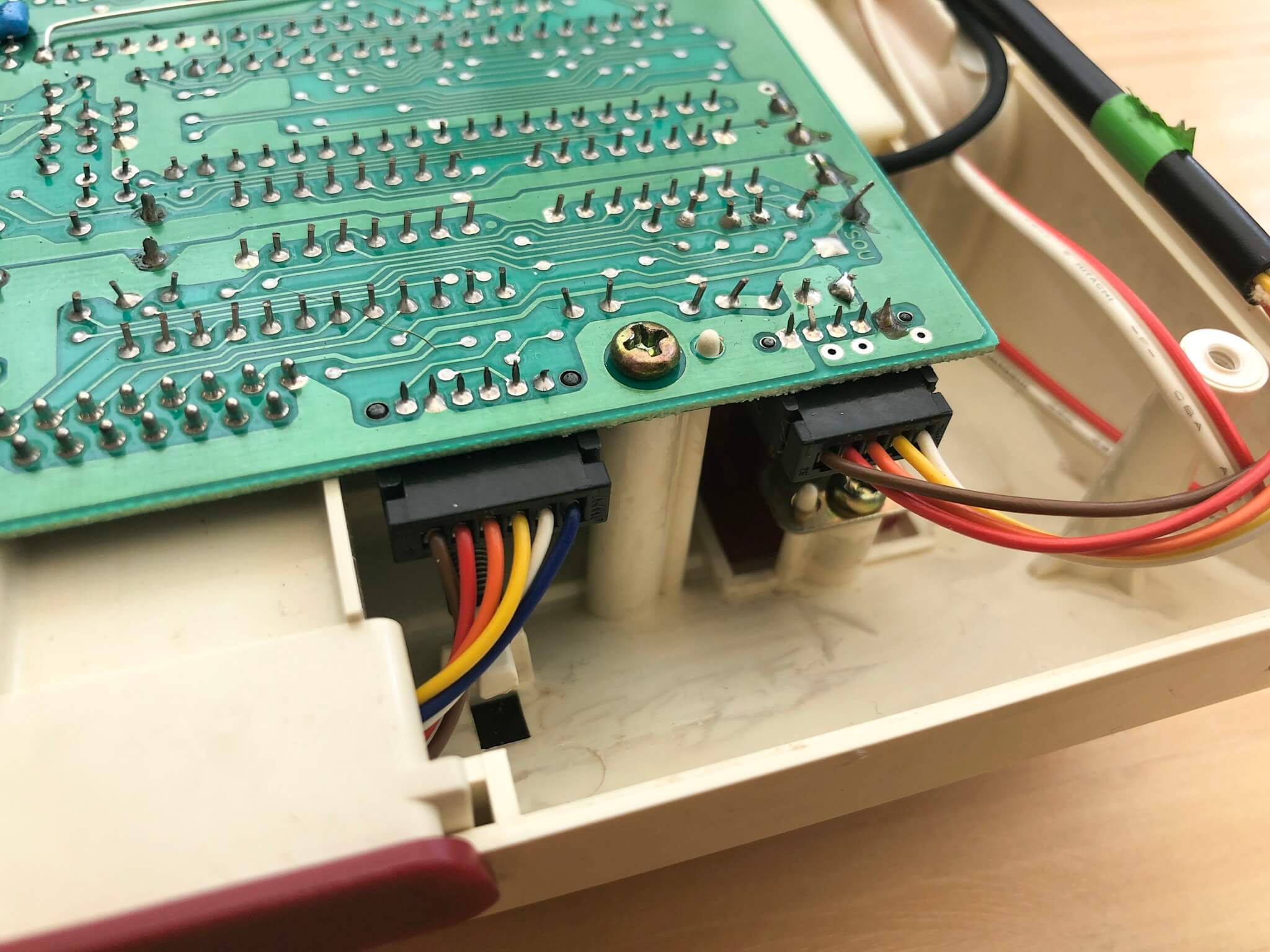
Remove the cables connected to the red and white switches that are soldered to the RF board.


Use a desoldering wire to remove the solder. You don't need to use the desoldering wire, as long as it comes off.


The switch has now been removed.
Installing the switch

Solder the cable of the switch you just removed to the "SWITCH" part of the FCAV board.
Separating the RF board
Separate the main board of the Famicom from the RF board. Cut the cable on the main board side.

Use nippers to cut it.

Remove the wires left after cutting with a soldering iron. (If it is difficult, you can leave them as they are.

Modification of the Famicom board
Adding Capacitors
Noise generated by memory access is mixed in the Famicom video. This is the vertical stripe noise. In the case of the old RF connection (connecting to the antenna wire), this noise was not so noticeable due to the degradation of the video caused by RF. However, when we modified the video circuit, the image became more beautiful, and the noise that was not noticeable before became more noticeable.
Therefore, in order to avoid noise from memory access as much as possible, we will add two capacitors to reduce the voltage fluctuation of the power supply and reduce the vertical stripe noise.

The first one
Install the first capacitor at this location in the photo.
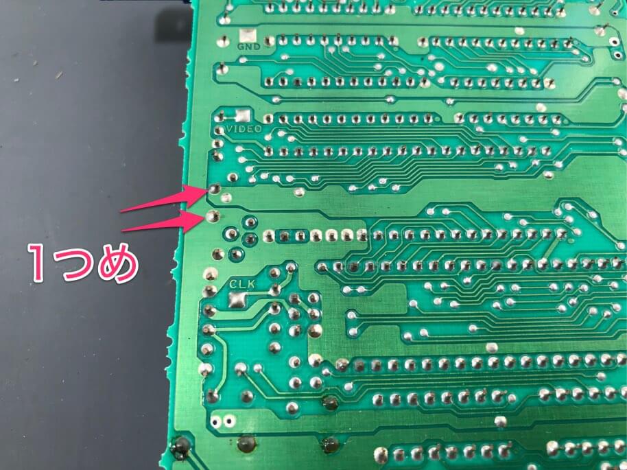

Cut off the excess legs with nippers.
Second one

Connect the arrows in the photo with the capacitor. Deform the shape of the capacitor so that the legs of the capacitor do not touch the silver solder around it. If it is too difficult, you don't need to install the second capacitor.

Mount the capacitor like this.
FCAV and Wiring

Place the main board of the Famicom and FCAV in the case. Place the main board in the original location and the FCAV in the location where the RF board was.

Wire the circled areas with the supplied solder-plated wires.

Connect only the five wires from the left as shown in the photo.
Putting it back together

Screw in each board.
Plug the connector of the controller into the board.

Put the back cover on and screw it on.
Modification complete

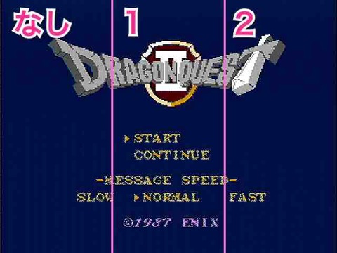
Connect the video cable, and confirm that the image is displayed on the TV, and the modification is complete. In the photo above, the video is projected to the PC using the capture cable.

You can now enjoy playing old, nostalgic games.