Hi, I'm kohanii.
A long time ago, I made a desk light (but I put it on the floor) to take notes at night.
I didn't write a blog about it at the time.

This is it.
The chicken toy is an eyesore, but don't let it bother you.
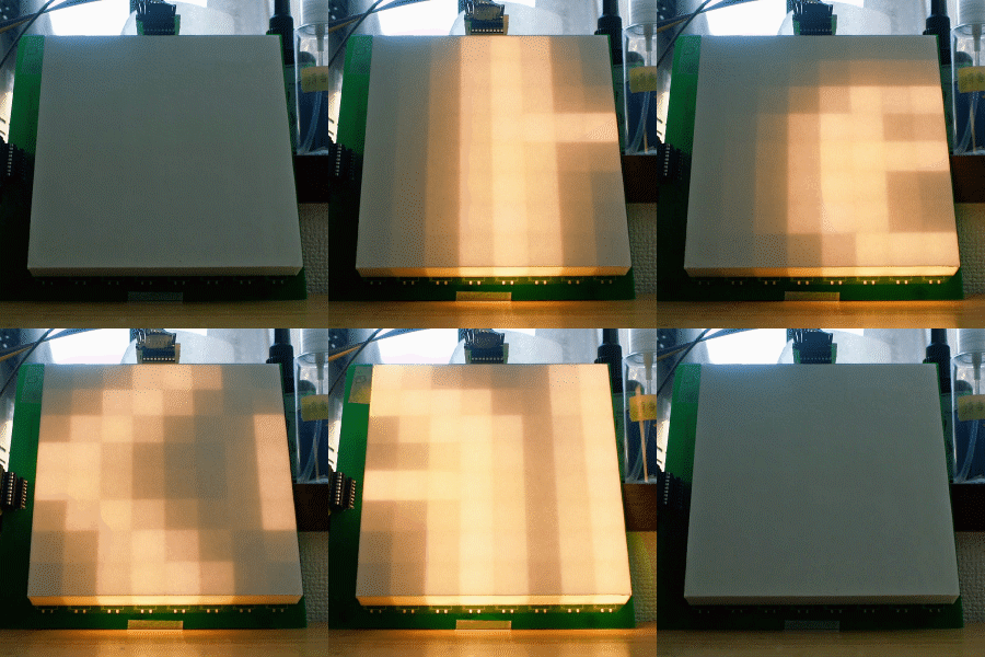
The brightness can be changed to three levels (25%, 50%, 100%) with a switch.
When I made this, I forgot to turn on the power switch, so if I want to turn it off, I have to remove the batteries.
For the main body, I simply attached a piece of driftwood I picked up at a nearby river to a wooden board I happened to have at home with a bond.
The only problem is that the battery runs out quickly and the color is bluish white, so it has been stored in a closet.
Now, for the time being, I will strip all the machinery and improve it.

LED

For the LED, I will use a high color rendering light bulb LED tape.
This is the bulb color version of the LED used in the following article.
Making LED cases with a 3D printer
Using this tape naked is not aesthetically pleasing, so I will use a 3D printer to make a case for it.

I just made it in Blender.

Slice with cura.

Printed with a 3D printer.

Ta-da!

The top hole is for the LED power cable.
The holes at the bottom are for screwing it to the wood.

The back of the LED tape is double-sided, so all I have to do is connect the wires and stick it on.

I can get the wires out from the back.
Diffuser
LEDs create multiple shadows due to point lighting, so I will create a diffuser to blur the light.

I could. This was also made with a 3D printer.

I covered it with the case. This will keep my eyes from burning.
Let's try shining a single LED for now


Here are the pictures from the front and back.
The light is quite blurry and seems to be easy on the eyes.
Making it glow with batteries
The power supply voltage for this LED tape is 12V.
The power supply is four AA batteries, about 6V.
If I have 8 batteries, I can get about 12V, but I don't have that many batteries.
So, I will use a boost DCDC converter.

I'll use the one I used in this article.
Can boost voltage from 5V input to 44V.
Schematic diagram
This time, remember to turn on the power switch.

A switch is inserted in series between the DCDC converter and the input power supply.
I want to adjust the brightness, so connect the DCDC converter to the volume.

Solder a cable from the back of the volume (RV2) of the DCDC converter and connect it to the volume (RV1).
I forgot the resistance value of the volume. I think it's about 1K to 10KΩ.
Reducing the resistance here seems to reduce the voltage.
Now, the brightness does not change linearly, but it can be dimmed.
Assembly

I soldered the slide volume and slide switch to the board, and also connected it to the battery box and DCDC converter.
It will work in this state, but I will use a hot bond to attach it to the body.

I attached the parts with hot glue. It's not easy to remove.
The circuit board is exposed, and it's not pretty, but it's okay.
The cover of the battery box has been removed for photographic purposes. Of course I didn't lose the battery box lid.
Done!!!
Here's a video.
z z z z ...
The end


