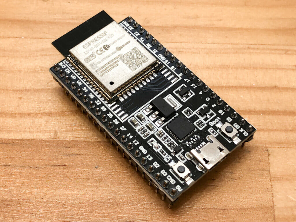
I'm designing a battery-powered ESP32-DevkitC. The ESP32-DevkitC can be powered in two ways: from USB or from an external power supply.

For the battery-powered ESP32-DevkitC, I would like to implement two power supply methods: USB and battery.
Super simple way to switch the power supply
When supplying electricity from two power sources, the simplest circuit is to connect the two power sources together.

There is a condition, however, that users should only connect one of them, either USB or battery. When supplying from USB, you must remove the battery, and when supplying from the battery, you must remove the USB.
This is because USB is 5V and battery is 3V, so if you connect USB and battery at the same time, electricity will flow from USB to battery, and not only the DCDC converter will not be supplied with power, but also the USB will be damaged due to excessive current flowing from USB to battery. This is the worst possible circuit, forcing inconvenience to the users.
So, one way to supply electricity from whichever voltage is higher is to OR it with a diode.

The input side of the diode is called the anode and the output side is called the cathode. Diodes have the property that current flows only in one direction, from the anode to the cathode.

Therefore, by connecting a diode as shown in the diagram above, even if a 5V USB and a 3V battery are connected at the same time, the electricity from the USB will not flow to the battery.
Also, in the case of this circuit ORed with diodes, the electricity is supplied from the higher voltage. In the case of 5V and 3V, electricity will be supplied from the 5V USB and not from the battery. Therefore, when the USB is connected, the battery electricity will not be consumed. When the USB is disconnected, electricity is seamlessly supplied from the battery.
Diodes lose voltage
You may think that the previous circuit is complete, but there is one problem. The electricity that goes through the diode will drop in voltage. In general, the voltage drops as it passes through the diode: 1V for a rectifier diode, 0.6V for a small signal diode, and about 0.4V for a Schottky barrier diode, which has a smaller drop.
For example, in the case of the 1N4007 rectifier diode, if you look at the data sheet

Look at the Forward Voltage column. The value is then 1.1V. When electricity passes through this diode, the voltage drops by 1.1V.
In the case of the Schottky barrier diode SB240LES,

The forward voltage is about 0.4V.
In this way, the voltage drops as it passes through the diode.
For example, suppose a Schottky barrier diode with a forward voltage of 0.4V is used in an OR circuit for power supply switching. In the case of USB 5V, the voltage drops only to 4.6V, so there is no problem with the operation of the DCDC in the later stage. However, for lower voltage batteries, problems can occur. The minimum operating voltage of the DCDC converter we are planning to use is 1.8V. In the case of dry cell batteries, the operation will stop when the voltage goes from 3V in the new state to 2.2V. In the case of a rechargeable battery, the starting voltage is only 2.4V, so a drop of 0.2V is enough to stop the operation of the DCDC converter. The forward voltage of the diode is a pretty big loss when the power supply is a low voltage battery. It will cause the DCDC converter to stop working even though the battery still has quite a bit of energy left.
Ideal Diode
Schematic
Ideal diodes are, as the name implies, diodes that operate ideally. How ideal is the diode that has no voltage drop and electricity flows when the anode voltage > cathode voltage.

The basic circuit is shown in the figure above. A comparator compares the input voltage with the output voltage, and the switch closes and electricity flows only when the input voltage > output voltage. Conversely, if the voltage at the output side is higher than the input voltage, the switch opens to prevent the reverse flow of electricity. Switches are generally MOS-FETs.
I want to make a simpler circuit
In fact, to actually make the circuit of the ideal diode, it is quite troublesome to find a comparator that operates at low voltage, to find a MOS-FET that turns on at low voltage, and to think of a circuit to drive the MOS-FET.
In that case, Digikey is for you.

There are useful things in the world, and there is already an electronic component called Ideal Diode, and Digikey has a category for it.

In that category, filter the "Current - Output" to 1A to 2A.

Now all you have to do is choose the one that looks good from the list.

There was the ideal diode in such a small package.

The datasheet shows that it operates from 1.5V to 5.5V, with a maximum continuous current of 1.5A. There is no forward voltage like a diode, instead there is only an ON resistance of about 100mΩ since the switch is a MOS-FET. It is also very easy to use. If you connect the /CE and GND pins to GND and don't use the ST pin, then it can be used as a diode. This device fits the condition perfectly. I decided on this one.
Automatic power switching circuit completed

I decided to use a Schottky barrier diode for the USB power supply and an ideal diode for the battery power supply to configure the OR circuit.
This enabled automatic power switching: power is supplied from the USB when the USB is connected, and power is supplied from the battery when the USB is disconnected. And thanks to the ideal diode, you can maximize the energy of the battery even when operating on the battery.
Again, I did not need to design a circuit like the previous DCDC converter circuit, but simply used a dedicated IC to create the circuit.